
User guide
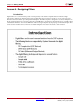
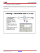
Table Of Contents
- Return to Menu
- System Generator for DSP
- Table of Contents
- About This Guide
- Introduction
- Installation
- Release Information
- Getting Started
- Introduction
- Lesson 1 - Design Creation Basics
- The System Generator Design Flow
- The Xilinx DSP Blockset
- Defining the FPGA Boundary
- Adding the System Generator Token
- Creating the DSP Design
- Generating the HDL Code
- Model-Based Design using System Generator
- Creating Input Vectors using MATLAB
- Lesson 1 Summary
- Lab Exercise: Using Simulink
- Lab Exercise: Getting Started with System Generator
- Lesson 2 - Fixed Point and Bit Operations
- Lesson 3 - System Control
- Lesson 4 - Multi-Rate Systems
- Lesson 5 - Using Memories
- Lesson 6 - Designing Filters
- Additional Examples and Tutorials
- Index
86 www.xilinx.com System Generator for DSP Getting Started Guide
UG639 (v 12.2) July 23, 2010
Chapter 4: Getting Started
Lesson 6 - Designing Filters
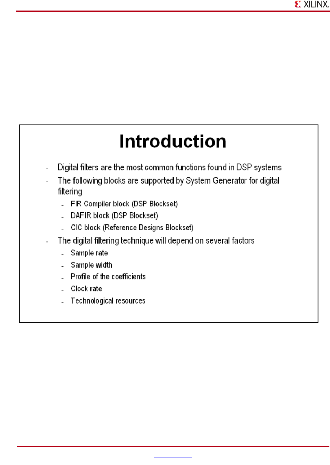
Introduction
Digital filters are a common DSP operation and especially well suited to implementation in FPGAs. High-
performance applications benefit greatly from parallel filters that can return a results on every clock cycle. The
Virtex®- 5 device includes up to 550 parallel multipliers. The FIR Compiler is designed to use these multipliers in
the most efficient manner for creating commonly used FIR filters. An alternative implementation is available called
“distributed arithmetic” that creates FIR filters without using multipliers by employing a shift-add technique. This
can be used for smaller devices when the available multipliers have been allocated to other functions.