
User guide
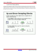
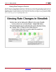
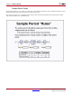
Table Of Contents
- Return to Menu
- System Generator for DSP
- Table of Contents
- About This Guide
- Introduction
- Installation
- Release Information
- Getting Started
- Introduction
- Lesson 1 - Design Creation Basics
- The System Generator Design Flow
- The Xilinx DSP Blockset
- Defining the FPGA Boundary
- Adding the System Generator Token
- Creating the DSP Design
- Generating the HDL Code
- Model-Based Design using System Generator
- Creating Input Vectors using MATLAB
- Lesson 1 Summary
- Lab Exercise: Using Simulink
- Lab Exercise: Getting Started with System Generator
- Lesson 2 - Fixed Point and Bit Operations
- Lesson 3 - System Control
- Lesson 4 - Multi-Rate Systems
- Lesson 5 - Using Memories
- Lesson 6 - Designing Filters
- Additional Examples and Tutorials
- Index
76 www.xilinx.com System Generator for DSP Getting Started Guide
UG639 (v 12.2) July 23, 2010
Chapter 4: Getting Started
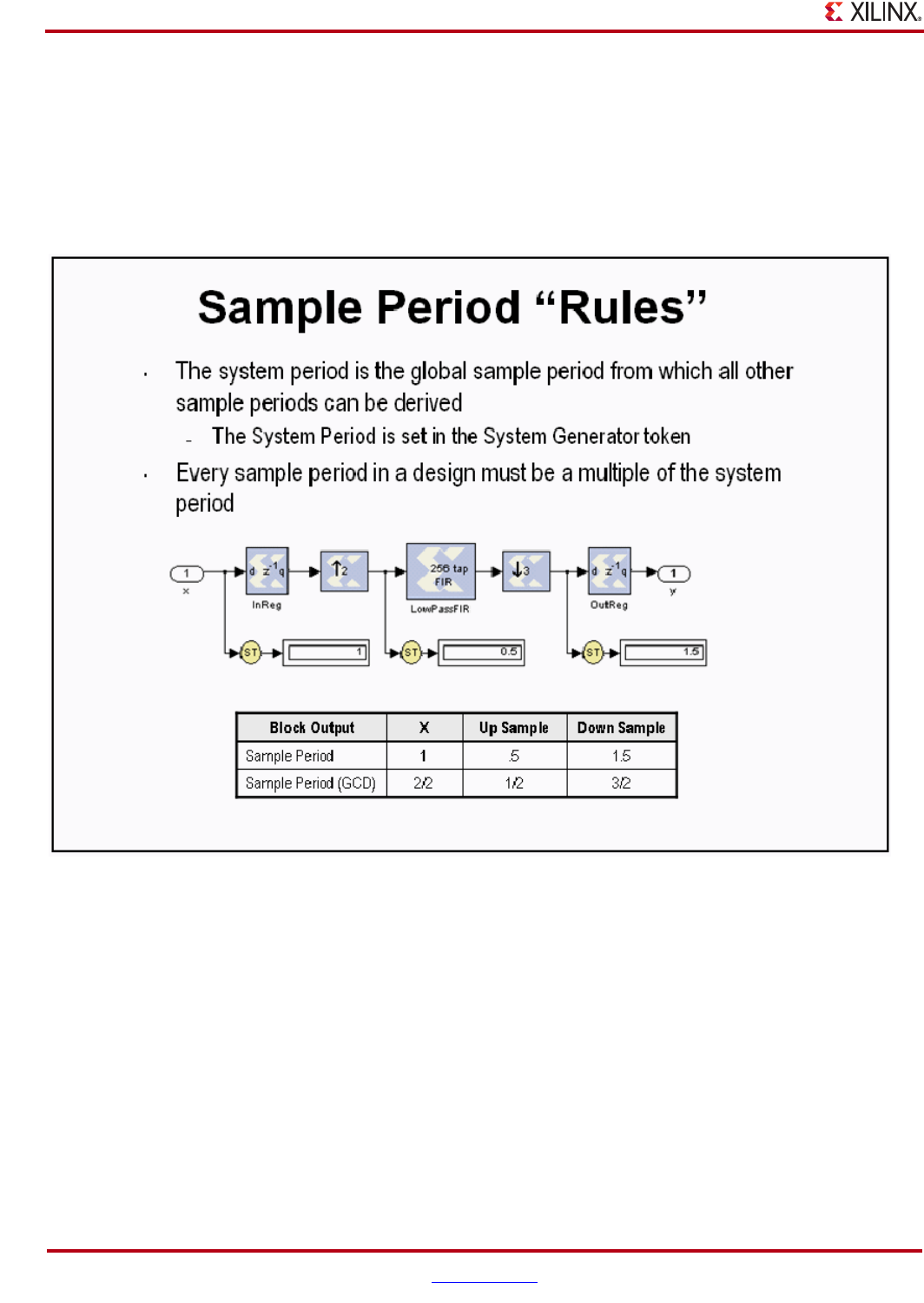
Sample Period “Rules”
The illustration below is an example of a multi-rate system that demonstrates how the Simulink System Period can
be calculated and entered into the System Generator token GUI.
If you get it wrong, there is a sampling period analyzer that automatically determines the appropriate sample
period and prompts you to update the GUI.