
User guide
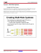
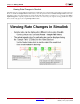
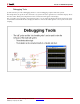
Table Of Contents
- Return to Menu
- System Generator for DSP
- Table of Contents
- About This Guide
- Introduction
- Installation
- Release Information
- Getting Started
- Introduction
- Lesson 1 - Design Creation Basics
- The System Generator Design Flow
- The Xilinx DSP Blockset
- Defining the FPGA Boundary
- Adding the System Generator Token
- Creating the DSP Design
- Generating the HDL Code
- Model-Based Design using System Generator
- Creating Input Vectors using MATLAB
- Lesson 1 Summary
- Lab Exercise: Using Simulink
- Lab Exercise: Getting Started with System Generator
- Lesson 2 - Fixed Point and Bit Operations
- Lesson 3 - System Control
- Lesson 4 - Multi-Rate Systems
- Lesson 5 - Using Memories
- Lesson 6 - Designing Filters
- Additional Examples and Tutorials
- Index
System Generator for DSP Getting Started Guide www.xilinx.com 75
UG639 (v 12.2) July 23, 2010
Lesson 4 - Multi-Rate Systems
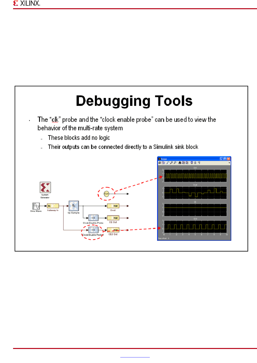
Debugging Tools
System Generator provides 3 debugging utilities to assist in debugging complex multi-rate systems.
The Sample Time (ST) probe can be connected to any System Generator signal then to a Simulink “display” block
from the “Sinks” library. The sample time for the connected net will appear in the display.
The clk probe is not connected to any inputs but only to a scope output. It displays the master clock. This can be
used with the Clock Enable Probe to display the behavior of the clock enable signal at various points in the down
sampling