
User guide
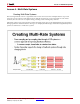
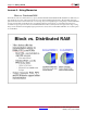
Table Of Contents
- Return to Menu
- System Generator for DSP
- Table of Contents
- About This Guide
- Introduction
- Installation
- Release Information
- Getting Started
- Introduction
- Lesson 1 - Design Creation Basics
- The System Generator Design Flow
- The Xilinx DSP Blockset
- Defining the FPGA Boundary
- Adding the System Generator Token
- Creating the DSP Design
- Generating the HDL Code
- Model-Based Design using System Generator
- Creating Input Vectors using MATLAB
- Lesson 1 Summary
- Lab Exercise: Using Simulink
- Lab Exercise: Getting Started with System Generator
- Lesson 2 - Fixed Point and Bit Operations
- Lesson 3 - System Control
- Lesson 4 - Multi-Rate Systems
- Lesson 5 - Using Memories
- Lesson 6 - Designing Filters
- Additional Examples and Tutorials
- Index
System Generator for DSP Getting Started Guide www.xilinx.com 71
UG639 (v 12.2) July 23, 2010
Lesson 4 - Multi-Rate Systems
Lesson 4 - Multi-Rate Systems
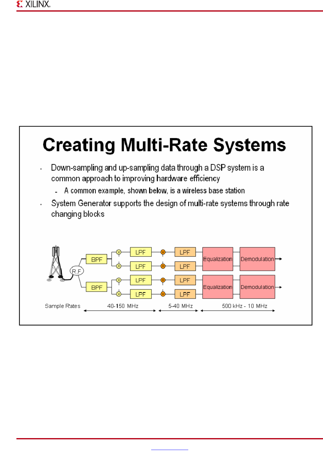
Creating Multi-Rate Systems
The following illustration shows a typical base-station receiver. The tower has multiple antennas to provide
sectored coverage of the area. The diagram shows that this results in two receiver channels. In each of these
channels, there is some form of complex mixing, resulting in real and imaginary channels.
Often DSP systems such as this will down sample the input signals prior to the digital filtering steps performed
during equalization and demodulation. Doing so can simplify the filter design and hardware significantly. These
systems are referred to as “multi-rate” systems