
User guide
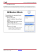
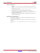
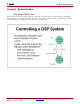
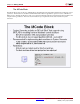
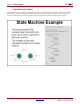
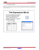
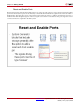
Table Of Contents
- Return to Menu
- System Generator for DSP
- Table of Contents
- About This Guide
- Introduction
- Installation
- Release Information
- Getting Started
- Introduction
- Lesson 1 - Design Creation Basics
- The System Generator Design Flow
- The Xilinx DSP Blockset
- Defining the FPGA Boundary
- Adding the System Generator Token
- Creating the DSP Design
- Generating the HDL Code
- Model-Based Design using System Generator
- Creating Input Vectors using MATLAB
- Lesson 1 Summary
- Lab Exercise: Using Simulink
- Lab Exercise: Getting Started with System Generator
- Lesson 2 - Fixed Point and Bit Operations
- Lesson 3 - System Control
- Lesson 4 - Multi-Rate Systems
- Lesson 5 - Using Memories
- Lesson 6 - Designing Filters
- Additional Examples and Tutorials
- Index
70 www.xilinx.com System Generator for DSP Getting Started Guide
UG639 (v 12.2) July 23, 2010
Chapter 4: Getting Started
Lesson 3 Summary
• Use the MCode block for state machines and branch conditional logic
• Use the Expression block to implement logical control at the bit level
• Storage elements have the ability to include optional reset and clock enable pins that
can be connected in System Generator
• Blocks that operate on bursty data include data flow control pins called vin and vout
Lab Exercise: System Control
In this lab you will be creating a simple state machine using the MCode block to detect a
sequence of binary values “1011”. The FSM needs to be able to detect multiple
transmissions as well, i.e., “10111011”
The lab data and instructions are located in the System Generator software tree at the
following pathname:
<ISE_Design_Suite_tree>/sysgen/examples/getting_started_training/lab4/