
User guide
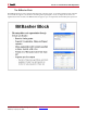
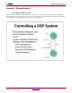
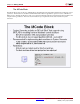
Table Of Contents
- Return to Menu
- System Generator for DSP
- Table of Contents
- About This Guide
- Introduction
- Installation
- Release Information
- Getting Started
- Introduction
- Lesson 1 - Design Creation Basics
- The System Generator Design Flow
- The Xilinx DSP Blockset
- Defining the FPGA Boundary
- Adding the System Generator Token
- Creating the DSP Design
- Generating the HDL Code
- Model-Based Design using System Generator
- Creating Input Vectors using MATLAB
- Lesson 1 Summary
- Lab Exercise: Using Simulink
- Lab Exercise: Getting Started with System Generator
- Lesson 2 - Fixed Point and Bit Operations
- Lesson 3 - System Control
- Lesson 4 - Multi-Rate Systems
- Lesson 5 - Using Memories
- Lesson 6 - Designing Filters
- Additional Examples and Tutorials
- Index
System Generator for DSP Getting Started Guide www.xilinx.com 69
UG639 (v 12.2) July 23, 2010
Lesson 3 - System Control
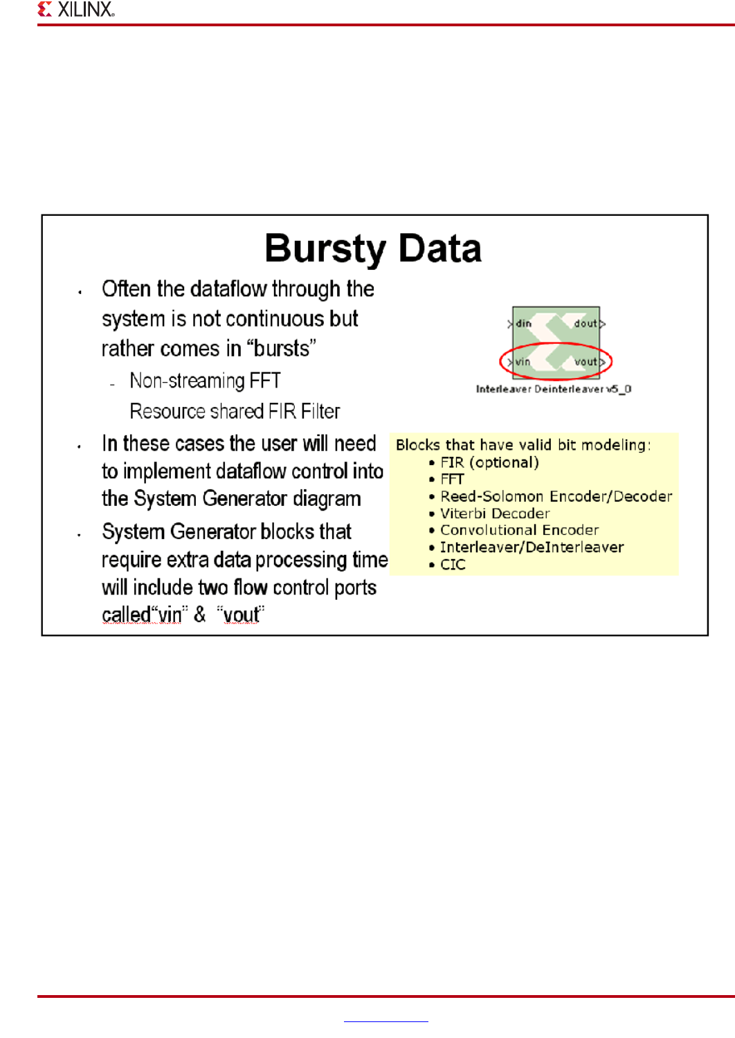
Bursty Data
Several of the more complex DSP blocks offered in the Xilinx DSP blockset result in “bursty” data. For example, the
non-streaming FFT requires several clock cycles to process the input data prior to generating valid output data. In
these cases, these blocks include data flow control ports that must be used in the DSP system. These ports provide
basic push mode dataflow control. They consist of a vin port which indicates that valid data is available at the
inputs and vout which indicates that valid data is available at the outputs.