
User guide
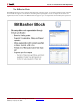
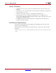
Table Of Contents
- Return to Menu
- System Generator for DSP
- Table of Contents
- About This Guide
- Introduction
- Installation
- Release Information
- Getting Started
- Introduction
- Lesson 1 - Design Creation Basics
- The System Generator Design Flow
- The Xilinx DSP Blockset
- Defining the FPGA Boundary
- Adding the System Generator Token
- Creating the DSP Design
- Generating the HDL Code
- Model-Based Design using System Generator
- Creating Input Vectors using MATLAB
- Lesson 1 Summary
- Lab Exercise: Using Simulink
- Lab Exercise: Getting Started with System Generator
- Lesson 2 - Fixed Point and Bit Operations
- Lesson 3 - System Control
- Lesson 4 - Multi-Rate Systems
- Lesson 5 - Using Memories
- Lesson 6 - Designing Filters
- Additional Examples and Tutorials
- Index
62 www.xilinx.com System Generator for DSP Getting Started Guide
UG639 (v 12.2) July 23, 2010
Chapter 4: Getting Started
Lesson 2 Summary
• Quantization and overflow options are available when the output of a block is user
defined
• Quantization occurs when the number of fractional bits is insufficient to represent the
fractional portion of a value
• Overflow occurs when a value lies outside the representable range
• Bit picking blocks allow combining of multiple buses into a single bus, force a
conversion of data type without changing the number of bits, extract bits, and convert
the number into different format
• The BitBasher block allows bit manipulation and augmentation through textual
specification based in Verilog
Lab Exercise: Signal Routing
In this lab you will design and verify padding and unpadding logic using the System
Generator signal routing blocks
The lab instructions are located in the System Generator software tree at the following
pathname:
<ISE_Design_Suite_tree>/sysgen/examples/getting_started_training/lab3/lab
3.pdf