
User guide
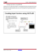
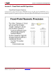
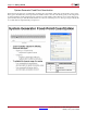
Table Of Contents
- Return to Menu
- System Generator for DSP
- Table of Contents
- About This Guide
- Introduction
- Installation
- Release Information
- Getting Started
- Introduction
- Lesson 1 - Design Creation Basics
- The System Generator Design Flow
- The Xilinx DSP Blockset
- Defining the FPGA Boundary
- Adding the System Generator Token
- Creating the DSP Design
- Generating the HDL Code
- Model-Based Design using System Generator
- Creating Input Vectors using MATLAB
- Lesson 1 Summary
- Lab Exercise: Using Simulink
- Lab Exercise: Getting Started with System Generator
- Lesson 2 - Fixed Point and Bit Operations
- Lesson 3 - System Control
- Lesson 4 - Multi-Rate Systems
- Lesson 5 - Using Memories
- Lesson 6 - Designing Filters
- Additional Examples and Tutorials
- Index
54 www.xilinx.com System Generator for DSP Getting Started Guide
UG639 (v 12.2) July 23, 2010
Chapter 4: Getting Started
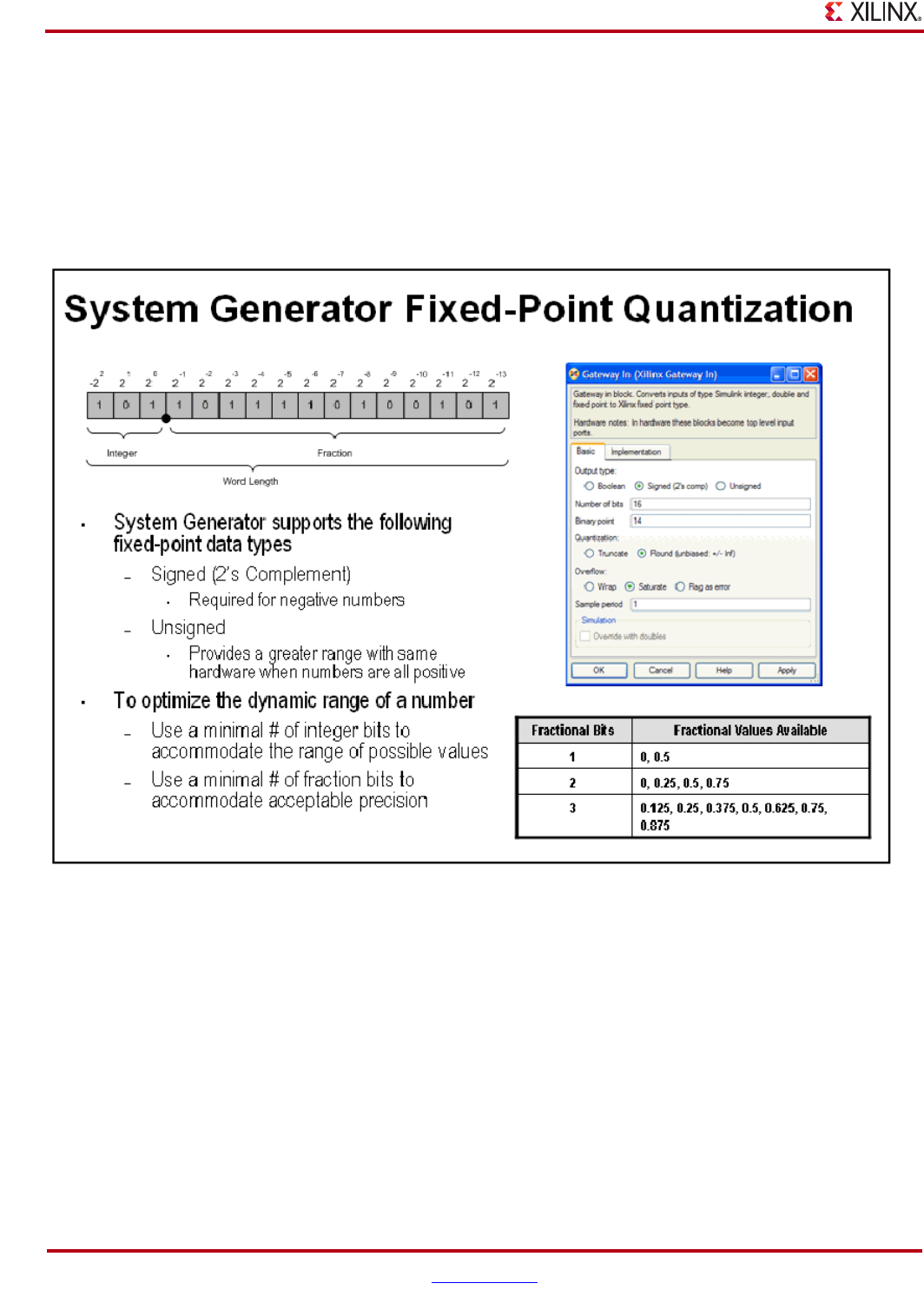
System Generator Fixed-Point Quantization
Xilinx fixed-point data types are defined by specifying the total number of bits then specifying the location of the
binary point. The difference, which represents the number of bits to the left of the binary point, are the integer bits
for ufixed numbers and the integer bits plus sign bit for signed numbers. Xilinx FPGAs do not require that fixed-
point numbers fall in pre-defined 8 bit boundaries as is the case with DSP processors. The logic can grow bit-by-bit
to accommodate the required fixed-point precision.