
User guide
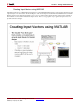
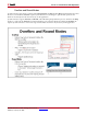
Table Of Contents
- Return to Menu
- System Generator for DSP
- Table of Contents
- About This Guide
- Introduction
- Installation
- Release Information
- Getting Started
- Introduction
- Lesson 1 - Design Creation Basics
- The System Generator Design Flow
- The Xilinx DSP Blockset
- Defining the FPGA Boundary
- Adding the System Generator Token
- Creating the DSP Design
- Generating the HDL Code
- Model-Based Design using System Generator
- Creating Input Vectors using MATLAB
- Lesson 1 Summary
- Lab Exercise: Using Simulink
- Lab Exercise: Getting Started with System Generator
- Lesson 2 - Fixed Point and Bit Operations
- Lesson 3 - System Control
- Lesson 4 - Multi-Rate Systems
- Lesson 5 - Using Memories
- Lesson 6 - Designing Filters
- Additional Examples and Tutorials
- Index
System Generator for DSP Getting Started Guide www.xilinx.com 51
UG639 (v 12.2) July 23, 2010
Lesson 1 - Design Creation Basics
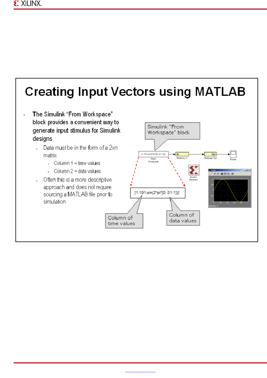
Creating Input Vectors using MATLAB
Simulink is built on top of MATLAB allowing the use of the full MATLAB language for input signal generation and
output analysis. You can use the “From Workspace” and “To Workspace” blocks from the Simulink Source and Sink
libraries. Input values must be specified as an n rows x 2 column matrix where the first column is the simulation
time and the second column includes the input values. This is a very popular way to generate input vectors for
System Generator designs.