
User guide
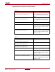
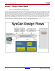
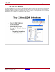
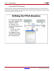
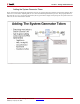
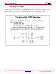
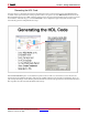
Table Of Contents
- Return to Menu
- System Generator for DSP
- Table of Contents
- About This Guide
- Introduction
- Installation
- Release Information
- Getting Started
- Introduction
- Lesson 1 - Design Creation Basics
- The System Generator Design Flow
- The Xilinx DSP Blockset
- Defining the FPGA Boundary
- Adding the System Generator Token
- Creating the DSP Design
- Generating the HDL Code
- Model-Based Design using System Generator
- Creating Input Vectors using MATLAB
- Lesson 1 Summary
- Lab Exercise: Using Simulink
- Lab Exercise: Getting Started with System Generator
- Lesson 2 - Fixed Point and Bit Operations
- Lesson 3 - System Control
- Lesson 4 - Multi-Rate Systems
- Lesson 5 - Using Memories
- Lesson 6 - Designing Filters
- Additional Examples and Tutorials
- Index
System Generator for DSP Getting Started Guide www.xilinx.com 49
UG639 (v 12.2) July 23, 2010
Lesson 1 - Design Creation Basics
Generating the HDL Code
Once the design is completed, the hardware implementation files can be generated using the Generate button
available on the System Generator token properties editor. One option is to select HDL Netlist which allows the
FPGA implementation steps of RTL synthesis and place and route to be performed interactively using tool specific
user interfaces. Alternatively, you can select Bitstream as the Compilation target and System Generator will
automatically perform all implementation steps.
If the Create Testbench option is selected, then System Generator will save and write test vector files that are
extracted from the Simulink simulation and generate an HDL testbench and script files for ModelSim. This is an
optional step that simply verifies that the generated hardware is functionally equivalent to the Simulink simulation.
The script files must be used with ModelSim interactively.