
User guide
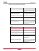
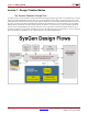
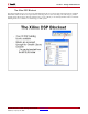
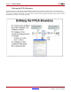
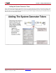
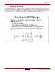
Table Of Contents
- Return to Menu
- System Generator for DSP
- Table of Contents
- About This Guide
- Introduction
- Installation
- Release Information
- Getting Started
- Introduction
- Lesson 1 - Design Creation Basics
- The System Generator Design Flow
- The Xilinx DSP Blockset
- Defining the FPGA Boundary
- Adding the System Generator Token
- Creating the DSP Design
- Generating the HDL Code
- Model-Based Design using System Generator
- Creating Input Vectors using MATLAB
- Lesson 1 Summary
- Lab Exercise: Using Simulink
- Lab Exercise: Getting Started with System Generator
- Lesson 2 - Fixed Point and Bit Operations
- Lesson 3 - System Control
- Lesson 4 - Multi-Rate Systems
- Lesson 5 - Using Memories
- Lesson 6 - Designing Filters
- Additional Examples and Tutorials
- Index
46 www.xilinx.com System Generator for DSP Getting Started Guide
UG639 (v 12.2) July 23, 2010
Chapter 4: Getting Started
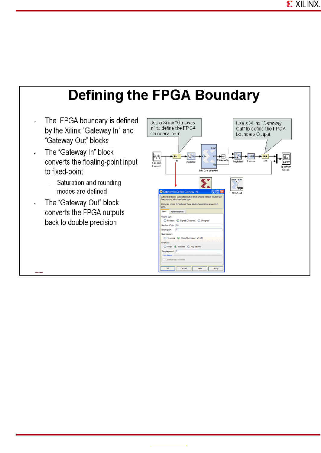
Defining the FPGA Boundary
System Generator works with standard Simulink models. Two blocks called “Gateway In” and “Gateway Out”
define the boundary of the FPGA from the Simulink simulation model. The Gateway In block converts the floating
point input to a fixed-point number. You double-click on the block to bring up the properties editor which is where
the fixed-point number can be fully specified.