
User guide
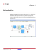
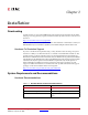
Table Of Contents
- Return to Menu
- System Generator for DSP
- Table of Contents
- About This Guide
- Introduction
- Installation
- Release Information
- Getting Started
- Introduction
- Lesson 1 - Design Creation Basics
- The System Generator Design Flow
- The Xilinx DSP Blockset
- Defining the FPGA Boundary
- Adding the System Generator Token
- Creating the DSP Design
- Generating the HDL Code
- Model-Based Design using System Generator
- Creating Input Vectors using MATLAB
- Lesson 1 Summary
- Lab Exercise: Using Simulink
- Lab Exercise: Getting Started with System Generator
- Lesson 2 - Fixed Point and Bit Operations
- Lesson 3 - System Control
- Lesson 4 - Multi-Rate Systems
- Lesson 5 - Using Memories
- Lesson 6 - Designing Filters
- Additional Examples and Tutorials
- Index
System Generator for DSP Getting Started Guide www.xilinx.com 11
UG639 (v 12.2) July 23, 2010
Chapter 1
Introduction
System Generator is a DSP design tool from Xilinx that enables the use of the MathWorks
model-based Simulink
® design environment for FPGA design. Previous experience with
Xilinx FPGAs or RTL design methodologies are not required when using System
Generator. Designs are captured in the DSP friendly Simulink modeling environment
using a Xilinx specific blockset. All of the downstream FPGA implementation steps
including synthesis and place and route are automatically performed to generate an FPGA
programming file.