System Generator for DSP Getting Started Guide UG639 (v 12.
Xilinx is disclosing this user guide, manual, release note, and/or specification (the "Documentation") to you solely for use in the development of designs to operate with Xilinx hardware devices. You may not reproduce, distribute, republish, download, display, post, or transmit the Documentation in any form or by any means including, but not limited to, electronic, mechanical, photocopying, recording, or otherwise, without the prior written consent of Xilinx.
Table of Contents Preface: About This Guide Guide Contents . . . . . . . . . . . . . . . . . . . . . . . . . . . . . . . . . . . . . . . . . . . . . . . . . . . . . . . . . . . . . . System Generator PDF Doc Set . . . . . . . . . . . . . . . . . . . . . . . . . . . . . . . . . . . . . . . . . . . . . . . Additional Resources . . . . . . . . . . . . . . . . . . . . . . . . . . . . . . . . . . . . . . . . . . . . . . . . . . . . . . . . Conventions . . . . . . . . . . . . . . . . . . . . . . . . . . . . . . .
Xilinx Blockset Enhancements . . . . . . . . . . . . . . . . . . . . . . . . . . . . . . . . . . . . . . . . . . . . . . 31 System Requirements and Recommendations . . . . . . . . . . . . . . . . . . . . . . . . . . . . . . . . 33 Known Issues . . . . . . . . . . . . . . . . . . . . . . . . . . . . . . . . . . . . . . . . . . . . . . . . . . . . . . . . . . . . 34 Release Notes 11.4 . . . . . . . . . . . . . . . . . . . . . . . . . . . . . . . . . . . . . . . . . . . . . . . . . . . . . . . . . . .
Up and Down Sampling Blocks . . . . . . . . . . . . . . . . . . . . . . . . . . . . . . . . . . . . . . . . . . . . . Rate Changing Functional Blocks . . . . . . . . . . . . . . . . . . . . . . . . . . . . . . . . . . . . . . . . . . . Viewing Rate Changes in Simulink . . . . . . . . . . . . . . . . . . . . . . . . . . . . . . . . . . . . . . . . . . Debugging Tools . . . . . . . . . . . . . . . . . . . . . . . . . . . . . . . . . . . . . . . . . . . . . . . . . . . . . . . . . Sample Period “Rules” . . . .
www.xilinx.com System Generator for DSP Getting Started Guide UG639 (v 12.
Preface About This Guide This Getting Started Guide introduces you to System Generator for DSP, then provides installation and configuration instructions, release information, and six mini-training modules that highlight the main features of the product. Each module starts with a lesson of 8-10 slides that explain important concepts, followed by a lab exercise that take about 30 minutes to complete.
Preface: About This Guide Additional Resources To find additional documentation, see the Xilinx website at: http://www.xilinx.com/support/documentation/index.htm. To search the Answer Database of silicon, software, and IP questions and answers, or to create a technical support WebCase, see the Xilinx website at: http://www.xilinx.com/support/mysupport.htm. Conventions This document uses the following conventions. An example illustrates each convention.
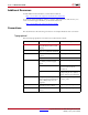
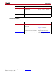
Conventions Convention Vertical ellipsis . . . Meaning or Use Repetitive material that has been omitted Horizontal ellipsis . . . Repetitive material that has been omitted Example IOB #1: Name = QOUT’ IOB #2: Name = CLKIN’ . . . allow block block_name loc1 loc2 ... locn; Online Document The following conventions are used in this document: Convention Blue text Meaning or Use Example Cross-reference link to a location in the current document See the topic “Additional Resources” for details.
Preface: About This Guide 10 www.xilinx.com System Generator for DSP Getting Started Guide UG639 (v 12.
Chapter 1 Introduction System Generator is a DSP design tool from Xilinx that enables the use of the MathWorks model-based Simulink® design environment for FPGA design. Previous experience with Xilinx FPGAs or RTL design methodologies are not required when using System Generator. Designs are captured in the DSP friendly Simulink modeling environment using a Xilinx specific blockset.
Chapter 1: Introduction The Xilinx DSP Block Set Over 90 DSP building blocks are provided in the Xilinx DSP blockset for Simulink. These blocks include the common DSP building blocks such as adders, multipliers and registers. Also included are a set of complex DSP building blocks such as forward error correction blocks, FFTs, filters and memories. These blocks leverage the Xilinx IP core generators to deliver optimized results for the selected device. 12 www.xilinx.
FIR Filter Generation FIR Filter Generation System Generator includes a FIR Compiler block that targets the dedicated DSP48 hardware resources in the Virtex®-4 and Virtex-5 devices to create highly optimized implementations that can run in excess of 500 Mhz. Configuration options allow generation of direct, polyphase decimation, polyphase interpolation and oversampled implementations.
Chapter 1: Introduction Support for MATLAB Included in System Generator is an MCode block that allows the use of non-algorithmic MATLAB for the modeling and implementation of simple control operations. 14 www.xilinx.com System Generator for DSP Getting Started Guide UG639 (v 12.
System Resource Estimation System Resource Estimation System Generator provides a Resource Estimator block that quickly estimates the area of a design prior to place and route. This can be a valuable aid in the hardware / software partitioning process by helping system designers take full advantage of the FPGA resources which include up to 640 multiply/accumulate (or DSP) blocks in the Virtex®-5 devices. System Generator for DSP Getting Started Guide UG639 (v 12.2) July 23, 2010 www.xilinx.
Chapter 1: Introduction Hardware Co-Simulation System Generator provides accelerated simulation through hardware co-simulation. System Generator will automatically create a hardware simulation token for a design captured in the Xilinx DSP blockset that will run on one of over 20 supported hardware platforms. This hardware will co-simulate with the rest of the Simulink system to provide up to a 1000x simulation performance increase. 16 www.xilinx.
System Integration Platform System Integration Platform System Generator provides a system integration platform for the design of DSP FPGAs that allows the RTL, Simulink, MATLAB and C/C++ components of a DSP system to come together in a single simulation and implementation environment. System Generator supports a black box block that allows RTL to be imported into Simulink and co-simulated with either ModelSim or Xilinx® ISE® Simulator.
Chapter 1: Introduction 18 www.xilinx.com System Generator for DSP Getting Started Guide UG639 (v 12.
Chapter 2 Installation Downloading System Generator is part of the ISE® Design Suite and may be download from the Xilinx web page. You may purchase, register, and download the System Generator software from the site at: http://www.xilinx.com/tools/sysgen.htm Note: In special circumstances, System Generator can be delivered on a CD. Please contact your Xilinx distributor if your circumstances prohibit you from downloading the software via the web.
Chapter 2: Installation Table 2-2: Linux-Based Hardware Recommendations Recommendation Notes 4 GB of RAM 600 MB of hard disk space Minimum Requirement Xilinx® Hardware Co-Simulation Platform Required for the Hardware Co-Simulation Flow Operating System and Software Requirements Table 2-3: Windows-Based Requirements Notes Windows XP Professional 32-bit/64-bit Operating System SP2 (English Only) A 32-bit Installation of System Generator requires a 32-bit Installation of MATLAB.
System Requirements and Recommendations Table 2-4: Linux-Based Requirements Notes SUSE Linux Enterprise (SLE) desktop and server v10.1, 32-bit/64-bit Operating System (English Only) A 32-bit Installation of System Generator requires a 32-bit Installation of MATLAB. A 64-bit Installation of System Generator requires a 64-bit Installation of MATLAB. Xilinx® ISE® Design Suite 12.2 MathWorks MATLAB® Version 2009b and 2010a MATLAB must be installed in a directory with no spaces (e.g., C:\MATLAB\R2010a).
Chapter 2: Installation Using the ISE Design Suite Installer Before invoking the ISE® Design Suite Installer, it is a good idea to make sure that all instances of MATLAB are closed. When all instances of MATLAB are closed, launch the installer and follow the directions on the screen.
Post Installation Tasks If the XML file is unreadable, the error message that is thrown to the MATLAB console is: Could not read ml_supported.xml to determine supported versions of MATLAB with System Generator xl_read_matlab_support_xmlfile This MATLAB function reads and parses the XML file looking for the supported MATLAB version information and provides error/warning messages used by the sysgen_startup.m script.
Chapter 2: Installation Note: If installation instructions for your particular platform are not provided here, please refer to the installation instuctions that come with your Platform Kit.
Post Installation Tasks Configuring the System Generator Cache Both the System Generator simulator and the design generator incorporate a disk cache to speed up the iterative design process. The cache does this by tagging and storing files related to simulation and generation, then recalling those files during subsequent simulation and generation rather than rerunning the time consuming tools used to create those files.
Chapter 2: Installation 26 www.xilinx.com System Generator for DSP Getting Started Guide UG639 (v 12.
Chapter 3 Release Information Release Notes 12.2 System Generator Enhancements System Generator 12.2 Performance Improvements • When opening a typical model in System Generator 12.2, you will see models open about 2x faster the first time compared to System Generator 12.1. For additional viewing of the model, you will typically see a 10x improvement compared to System Generator 12.1. • When opening System Generator blocks such as the FFT, FIR Compiler, and DDS Compiler in Release 12.
Chapter 3: Release Information Reed Solomon Encoder 7.1 • Restored support for the Spartan-6 device family. System Requirements and Recommendations Hardware Recommendations Recommendation Notes 2.
Release Notes 12.2 Table 3-2: Linux-Based Requirements Red Hat Enterprise Linux WS v4.7, 32-bit/64 bit Operating System Notes A 32-bit Installation of System Generator requires a 32-bit Installation of MATLAB. A 64-bit Installation of System Generator requires a 64-bit Installation of MATLAB. Red Hat Enterprise Desktop 5.2, 32-bit/64-bit Operating System A 32-bit Installation of System Generator requires a 32-bit Installation of MATLAB.
Chapter 3: Release Information Release Notes 12.
Release Notes 12.1 System Generator & Software Development Kit (SDK) Co-Debug (Beta Feature) Xilinx ISE® Design Suite 12.1 includes a new beta feature that introduces key improvements in the integration flow between System Generator, Xilinx Platform Studio (XPS), and Software Development Kit (SDK).
Chapter 3: Release Information Convert • An enable port has been added to the block interface. DSP48 Macro 2.0 • Fixed the simulation of the DSP48 Macro when it is configured with zero latency i.e. the block has a combinatorial path from input to output. FIR Compiler 5.0 • Fixed the issue with incorrect output binary point for dout port when rounding is being used for the output. • Fixed the issue with incorrect settings being saved on the block if the coefficient vector was not defined.
Release Notes 12.1 Automatic Normalization The input and output sample rates on the following blocks are now automatically normalized. There is no longer a need to add external rate-changing blocks to achieve this normalization. • Interleaver Deinterleaver 6.0 • Convolution Encoder 7.0 • Reed Solomon Decoder 7.0 • Reed Solomon Encoder 7.0 System Requirements and Recommendations Hardware Recommendations Recommendation Notes 2.
Chapter 3: Release Information Table 3-3: Windows-Based Requirements Notes MathWorks MATLAB® Version 2009a or 2009b MATLAB must be installed in a directory with no spaces (e.g., C:\MATLAB\R2009a) Fixed-Point Toolbox required for signals greater than 53 bits MathWorks Simulink with Fixed-Point Toolbox Version 2009a or 2009b MATLAB must be installed in a directory with no spaces (e.g.
Release Notes 11.4 Release Notes 11.4 System Generator Enhancements New Device Support • Spartan®-6 Low Power • Spartan-6 XA New Platform Support System Generator now supports Ethernet Hardware Co-Simulation for the Virtex®-6 ML605 Platform Xilinx Blockset Enhancements New Blocks DSP48 Macro 2.
Chapter 3: Release Information • Support has been added for all features in the underlying LogiCORE including the puncturing feature. Note: This block supersedes the Convolutional Encoder v6_1 block. The Convolution Encoder 7.0 block presents the same customization and port interface that is available in the underlying LogiCORE. The aclr input port has been removed. Interleaver Deinterleaver 5.1 • Support added for Spartan-3A DSP Note: This block supersedes the Interleaver Deinterleaver v5_0 block.
Release Notes 11.
Chapter 3: Release Information Table 3-6: Linux-Based Requirements Notes MathWorks MATLAB® Version 2009a or 2009b MATLAB must be installed in a directory with no spaces (e.g., C:\MATLAB\R2009a) Fixed-Point Toolbox required for signals greater than 53 bits MathWorks MATLAB®, Simulink with FixedPoint Toolbox Version 2009a and 2009b MATLAB must be installed in a directory with no spaces (e.g., C:\MATLAB\R2009a) Fixed-Point Toolbox required for signals greater than 53 bits 38 www.xilinx.
Release Notes 11.3 Release Notes 11.3 System Generator Enhancements New Device Support • Virtex®-6 Lower Power (Virtex-6 -1L) • Virtex-6 HXT • Virtex-5Q New Platform Support System Generator now supports JTAG HW co-simulation for the Spartan®-6 SP605 Platform New Operating System Support Full support for the following operating systems has been added: • Windows Vista Business 32-bit (English) • Red Hat Enterprise Desktop 5.
Chapter 3: Release Information • Option to configure DDS using system-level parameters (SFDR and frequency resolution) or hardware parameters (phase and output width) • Option to configure phase increment and phase offset as constant, programmable or dynamic (for modulation) Note: This block supersedes the DDS Compiler 3.0 block. DDS Compiler 4.0 is not bit-accurate with respect to earlier versions.
Release Notes 11.
Chapter 3: Release Information 42 www.xilinx.com System Generator for DSP Getting Started Guide UG639 (v 12.
Chapter 4 Getting Started Introduction This Getting Started training consists of six short lessons that introduce you to major features of System Generator for DSP. Each lesson takes less than 10 minutes to read and is followed by one or more hands-on lab exercises. The lab exercise folders are located in the System Generator software tree and contain data files and step-by-step instructions.
Chapter 4: Getting Started Lesson 1 - Design Creation Basics The System Generator Design Flow System Generator works within the Simulink model-based design methodology. Often an executable spec is created using the standard Simulink block sets. This spec can be designed using floating-point numerical precision and without hardware detail. Once the functionality and basic dataflow issues have been defined, System Generator can be used to specify the hardware implementation details for the Xilinx devices.
Lesson 1 - Design Creation Basics The Xilinx DSP Blockset The Xilinx DSP blockset is accessed via the Simulink Library browser which can be launched from the standard MATLAB toolbar. The blocks are separated into sub-categories for easier searching. One sub-category, “Index” includes all the block and is often the quickest way to access a block you are already familiar with. Over 90 DSP building blocks are available for constructing you DSP system.
Chapter 4: Getting Started Defining the FPGA Boundary System Generator works with standard Simulink models. Two blocks called “Gateway In” and “Gateway Out” define the boundary of the FPGA from the Simulink simulation model. The Gateway In block converts the floating point input to a fixed-point number. You double-click on the block to bring up the properties editor which is where the fixed-point number can be fully specified. 46 www.xilinx.com System Generator for DSP Getting Started Guide UG639 (v 12.
Lesson 1 - Design Creation Basics Adding the System Generator Token Every System Generator diagram requires that at least one System Generator token be placed on the diagram. This token is not connected to anything but serves to drive the FPGA implementation process. The property editor for this token allows you to specify the target netlist, device, performance targets and system period. System Generator will issue an error if this token is absent.
Chapter 4: Getting Started Creating the DSP Design Once the FPGA boundaries have been established using the Gateway blocks, the DSP design can be constructed using blocks from the Xilinx DSP blockset. Standard Simulink blocks are not supported for use within the Gateway In / Gateway out blocks. You will find a rich set of filters, FFTs, FEC cores, memories, arithmetic, logical and bitwise blocks available for use in constructing DSP designs. Each of these blocks are cycle and bit accurate. 48 www.xilinx.
Lesson 1 - Design Creation Basics Generating the HDL Code Once the design is completed, the hardware implementation files can be generated using the Generate button available on the System Generator token properties editor. One option is to select HDL Netlist which allows the FPGA implementation steps of RTL synthesis and place and route to be performed interactively using tool specific user interfaces.
Chapter 4: Getting Started Model-Based Design using System Generator Model-based design refers the design practice of creating a high-level executable specification using the standard Simulink blocksets or MATLAB first to define the desired functional behavior with minimal hardware detail. This executable spec is then used as a reference model while the hardware representation is specified using the Xilinx DSP blockset. 50 www.xilinx.com System Generator for DSP Getting Started Guide UG639 (v 12.
Lesson 1 - Design Creation Basics Creating Input Vectors using MATLAB Simulink is built on top of MATLAB allowing the use of the full MATLAB language for input signal generation and output analysis. You can use the “From Workspace” and “To Workspace” blocks from the Simulink Source and Sink libraries. Input values must be specified as an n rows x 2 column matrix where the first column is the simulation time and the second column includes the input values.
Chapter 4: Getting Started Lesson 1 Summary • You partition the FPGA design from the Simulink “system” using Gateway In / Gateway Out blocks. • You always include a System Generator token on each sheet • You should only use blocks from the Xilinx DSP blockset between the gateway blocks • You should consider using the From / To workspace blocks to use MATLAB for input generation and output analysis Lab Exercise: Using Simulink In this lab, you will learn the basics of Simulink.
Lesson 2 - Fixed Point and Bit Operations Lesson 2 - Fixed Point and Bit Operations Fixed-Point Numeric Precision System Generator supports three data types, Unsigned for positive only DSP operations, Signed which is two’s complement used for DSP operations that involve negative numbers and Boolean for 1-bit control signals. Each block will typically have quantization parameters. The initial quantization is defined by the Gateway In blocks. System Generator for DSP Getting Started Guide UG639 (v 12.
Chapter 4: Getting Started System Generator Fixed-Point Quantization Xilinx fixed-point data types are defined by specifying the total number of bits then specifying the location of the binary point. The difference, which represents the number of bits to the left of the binary point, are the integer bits for ufixed numbers and the integer bits plus sign bit for signed numbers. Xilinx FPGAs do not require that fixedpoint numbers fall in pre-defined 8 bit boundaries as is the case with DSP processors.
Lesson 2 - Fixed Point and Bit Operations Overflow and Round Modes System Generator supports the overflow modes Wrap, Saturate and Flag as error. Wrap is the default because it has the least cost in hardware. Saturate requires System Generator to insert logic to perform that operation and therefore should only be used when necessary for the application System Generator supports Truncate and Round of the LSB during the quantization process.
Chapter 4: Getting Started Bit-Level Operations In a real DSP hardware system, not all operations can be expressed mathematically. Often a signal must be accessed by its individual bits. System Generator supports a set of bit-level operations that allow the reinterpret, combining, conversion and extraction of the individual bits of a signal. This can be used to pad, unpad and slice off the bits of a signal with a high degree of control. These blocks do not use any hardware resources 56 www.xilinx.
Lesson 2 - Fixed Point and Bit Operations The Reinterpret Block The Reinterpret block forces the bits of a signal to a new type without regard for the numerical value or location of the decimal point. This block does not change the number of bits of a signal but simply reinterprets the data type. For example if the number 4 is represented as an unsigned [4 1] it is 1000. If this number is reinterpreted to be unsigned [4 0], the 1000 is now 8. System Generator for DSP Getting Started Guide UG639 (v 12.
Chapter 4: Getting Started The Convert Block The Convert block changes the quantization of a number but not the value. This block can alter the number of bits used to represent a number. It can be used to convert a signed type to an unsigned type and visa versa. Often the Convert block is used to truncate the output fractional bits after a multiplication operation. 58 www.xilinx.com System Generator for DSP Getting Started Guide UG639 (v 12.
Lesson 2 - Fixed Point and Bit Operations The Concat Block The Concat block concatenates two inputs into a single output at the bit level. This block has two input ports that are labeled hi and lo. The hi port occupies the MSB’s and the lo input occupies the LSB’s of the output signal. This block is useful for zero padding the MSBs or LSBs of a signal. System Generator for DSP Getting Started Guide UG639 (v 12.2) July 23, 2010 www.xilinx.
Chapter 4: Getting Started Slice Block The Slice block is used to access individual bits of a quantized number. This block provides several mechanisms by which the sequence of bits can be specified. If the input type is known at the time of parameterization, the various mechanisms do not offer any gain in functionality. If, however, a Slice block is used in a design where the input data width or binary point position are subject to change, the variety of mechanisms becomes useful.
Lesson 2 - Fixed Point and Bit Operations The BitBasher Block The BitBasher block provides a textual method, based on Verilog syntax, for working with the signals at the bit level. This block supports concatenation and slicing if the input signal to create an output. It also allows for augmentation with constants. The BitBasher block supports up to 4 outputs that are inferred by the expressions System Generator for DSP Getting Started Guide UG639 (v 12.2) July 23, 2010 www.xilinx.
Chapter 4: Getting Started Lesson 2 Summary • Quantization and overflow options are available when the output of a block is user defined • Quantization occurs when the number of fractional bits is insufficient to represent the fractional portion of a value • Overflow occurs when a value lies outside the representable range • Bit picking blocks allow combining of multiple buses into a single bus, force a conversion of data type without changing the number of bits, extract bits, and convert the number
Lesson 3 - System Control Lesson 3 - System Control Controlling a DSP System When you develop a DSP system in hardware, some level of control is usually required. This may include state dependent behavior or simply performing operations such as filter coefficient updating. System-level control may also be needed for controlling bursty data such as non-streaming FFTs. System Generator for DSP Getting Started Guide UG639 (v 12.2) July 23, 2010 www.xilinx.
Chapter 4: Getting Started The MCode Block The MCode block supports the use of MATLAB for implementing state dependent and branch conditional control operations. This block is not suitable for MATLAB that describes an algorithmic operation such as a FIR filter or Matrix inverse. The MCode block provides a convenient and efficient method for implementing state machines and complex muxing conditions. This is the recommended way to implement a finite state machine in System Generator. 64 www.xilinx.
Lesson 3 - System Control The Xilinx “xl_state” Data Type When implementing a state machine using the MCode block, a Xilinx-provided MATLAB function called “xl_state” must be used to initialize a persistent variable. This function has two arguments, the first is the initial condition, the second is the quantization of the assigned variable. For example, if your state machine has 6 states, you need a quantization of 4-bits unsigned. System Generator for DSP Getting Started Guide UG639 (v 12.
Chapter 4: Getting Started State Machine Example The figure below shows a simple 2-state FSM. This can be easily extended to more states. Notice that a variable called “state” is declared to be persistent and is initialized to 2 bits, unsigned using the “xl_state” function. A switch-case statement is then used to decode the inputs, branch to the next state and assign the outputs. 66 www.xilinx.com System Generator for DSP Getting Started Guide UG639 (v 12.
Lesson 3 - System Control The Expression Block The Expression block performs a bitwise not, and, or & xor on two input signals. The inputs can have a word length greater than 1. In cases where the two inputs have different word lengths, the binary points are matched up and then an element-by-element boolean operation is performed. This block provides a useful way to implement logical control in a DSP system System Generator for DSP Getting Started Guide UG639 (v 12.2) July 23, 2010 www.xilinx.
Chapter 4: Getting Started Reset and Enable Ports Most System Generator blocks that include memory or storage provide options to expose the reset and clock enable ports. If un-selected, these ports are automatically connected to the final hardware's global reset and clock enable or DCM schemes. Exposing these ports on the System Generator block creates a condition where the block is reset or enabled when either the global signals or the local signals assert TRUE.
Lesson 3 - System Control Bursty Data Several of the more complex DSP blocks offered in the Xilinx DSP blockset result in “bursty” data. For example, the non-streaming FFT requires several clock cycles to process the input data prior to generating valid output data. In these cases, these blocks include data flow control ports that must be used in the DSP system. These ports provide basic push mode dataflow control.
Chapter 4: Getting Started Lesson 3 Summary • Use the MCode block for state machines and branch conditional logic • Use the Expression block to implement logical control at the bit level • Storage elements have the ability to include optional reset and clock enable pins that can be connected in System Generator • Blocks that operate on bursty data include data flow control pins called vin and vout Lab Exercise: System Control In this lab you will be creating a simple state machine using the MCode b
Lesson 4 - Multi-Rate Systems Lesson 4 - Multi-Rate Systems Creating Multi-Rate Systems The following illustration shows a typical base-station receiver. The tower has multiple antennas to provide sectored coverage of the area. The diagram shows that this results in two receiver channels. In each of these channels, there is some form of complex mixing, resulting in real and imaginary channels.
Chapter 4: Getting Started Up and Down Sampling Blocks System Generator includes Up Sample and Down Sample blocks that change the system sample rate. The Up Sample block adds additional samples to the signal to achieve the desired rate change. The value of these new samples is either zero or the value of the last actual sample depending on the block options. The Down Sample block simply discards samples until it achieves the desired rate change.
Lesson 4 - Multi-Rate Systems Rate Changing Functional Blocks In addition to the straightforward “Up Sample” and “Down Sample” blocks, System Generator also provides rate changing functional blocks; that is blocks that also perform a specific function. The Parallel to Serial block will up sample, the Serial to Parallel block will down sample, the FIR Compiler, if using a resource-shared multiplier will down sample and the TDM block will up sample.
Chapter 4: Getting Started Viewing Rate Changes in Simulink Simulink supports viewing different sample times as different colors which is fully supported for System Generator blocks. To enable the Sample Time Colors feature, select the pulldown menu Format > Sample Time Colors. The Simulink tool does not automatically recolor the model with each change you make to it, so you must select Edit > Update Diagram to explicitly update the model coloration.
Lesson 4 - Multi-Rate Systems Debugging Tools System Generator provides 3 debugging utilities to assist in debugging complex multi-rate systems. The Sample Time (ST) probe can be connected to any System Generator signal then to a Simulink “display” block from the “Sinks” library. The sample time for the connected net will appear in the display. The clk probe is not connected to any inputs but only to a scope output. It displays the master clock.
Chapter 4: Getting Started Sample Period “Rules” The illustration below is an example of a multi-rate system that demonstrates how the Simulink System Period can be calculated and entered into the System Generator token GUI. If you get it wrong, there is a sampling period analyzer that automatically determines the appropriate sample period and prompts you to update the GUI. 76 www.xilinx.com System Generator for DSP Getting Started Guide UG639 (v 12.
Lesson 4 - Multi-Rate Systems Lab Exercise: Multi-Rate Systems In this lab you will be exploring the effects of the rate changing blocks available in System Generator. These blocks include Upsample, Downsample, Serial to Parallel and Parallel to Serial. The lab instructions and lab design are located in the System Generator software tree at the following pathname: /sysgen/examples/getting_started_training/lab5/ System Generator for DSP Getting Started Guide UG639 (v 12.
Chapter 4: Getting Started Lesson 5 - Using Memories Block vs. Distributed RAM Xilinx FPGAs offer two distinct memory options, Block RAM and Distributed RAM. Block RAM uses dedicated, onchip, hardware resources and represents the most area-efficient RAM implementation. Block RAMs offer high performance but due to their fixed location on the chip, may incur slightly larger routing delays.
Lesson 5 - Using Memories Initializing RAMs and ROMs The RAM and ROM blocks can be initialized to a 1xn vector that matches the depth of the RAM. MATLAB is used to set the initial value vector. Any MATLAB statement can be used that results in a 1xn vector including the file reading commands such as imread, auread, wavread, and load. System Generator for DSP Getting Started Guide UG639 (v 12.2) July 23, 2010 www.xilinx.
Chapter 4: Getting Started System Generator RAM Blocks System Generator provides both a single- and dual-port RAM block. Depths up to 64K are supported. Both Distributed RAM and Block RAM implementation options are available. System Generator calls the Xilinx memory compiler to create an efficient memory structure in hardware for the given parameters, bit widths and depths. You don’t need to be concerned with the hardware details of the specific Virtex® block or Distributed RAM structure.
Lesson 5 - Using Memories System Generator ROM Blocks The ROM block supports an implementation in either Block- or Distributed RAM and is initialized through a MATLAB command. The signal connected to the address port must be unsigned with no fractional bits System Generator for DSP Getting Started Guide UG639 (v 12.2) July 23, 2010 www.xilinx.
Chapter 4: Getting Started The Delay Block The Delay block is used to synchronize dataflow through the FPGA. This block maps to a highly-efficient shift register structure built from a slice lookup table called an SRL16 that is 85% smaller than using registers. 82 www.xilinx.com System Generator for DSP Getting Started Guide UG639 (v 12.
Lesson 5 - Using Memories The FIFO Block The FIFO block supports both Block RAM and Distributed RAM implementations. Depths up to 64K are supported. Three output flags are supported, empty, full and %full. The %full flag is set depending on a bit width specification. One bit will be zero until the FIFO is 50% full, then it will set to.5. Two bits will be zero until 20% full, then .25, .5 and .75. System Generator for DSP Getting Started Guide UG639 (v 12.2) July 23, 2010 www.xilinx.
Chapter 4: Getting Started Shared Memory Block System Generator provides a simple abstraction for easily adding custom logic into a processor. The basic idea is to allow memories in custom logic to be easily mapped into the processor's memory address space. System Generator enables this through the use of Shared-Memory blocks provided in the System Generator block set. 84 www.xilinx.com System Generator for DSP Getting Started Guide UG639 (v 12.
Lesson 5 - Using Memories Lab Exercise: Using Memories In this lab you will learn how to use a Xilinx ROM block to implement a LUT-based operation such as an Arcsin using Block RAM or Distributed RAM. This provides an efficient implementation for trig and math functions with inputs that can be quantized to 10 bits or less.
Chapter 4: Getting Started Lesson 6 - Designing Filters Introduction Digital filters are a common DSP operation and especially well suited to implementation in FPGAs. Highperformance applications benefit greatly from parallel filters that can return a results on every clock cycle. The Virtex®- 5 device includes up to 550 parallel multipliers. The FIR Compiler is designed to use these multipliers in the most efficient manner for creating commonly used FIR filters.
Lesson 6 - Designing Filters The Virtex DSP48 Math Slice The Virtex® family introduces a high-performance arithmetic unit along with a multiplier: the low-power DSP48 slice. The following figure is a detailed diagram of the DSP48 structure. The DSP48 slice consists of four main sections: (1) I/O registers, (2) signed multiplier, (3) three-input adder/subtractor, and (4) OPMODE multiplexers. System Generator for DSP Getting Started Guide UG639 (v 12.2) July 23, 2010 www.xilinx.
Chapter 4: Getting Started FIR Compiler Block The Xilinx Fir Compiler block implements a high speed MAC based FIR filter. It accepts a stream of input data and computes filtered output with a fixed delay, based on the filter configuration. The FIR Compiler supports generation of resource shared or parallel FIR structures and polyphase decimation and interpolation structures. Also supported is oversampling. Coefficients are specified using MATLAB commands. 88 www.xilinx.
Lesson 6 - Designing Filters Creating Coefficients with FDATool The MathWorks FDATool is a graphical filter design program that can be used to generate coefficients for the FIR Compiler block. The Xilinx FDATool block provides an interface to the FDATool software available as part of the MATLAB Signal Processing Toolbox. In order for this block to function properly, the Signal Processing Toolbox must be installed. System Generator for DSP Getting Started Guide UG639 (v 12.2) July 23, 2010 www.xilinx.
Chapter 4: Getting Started Using FDA Tool Coefficients Once a suitable filter response has been designed, you simply export the coefficients to the workspace using the File > Export command. The workspace variable can then be referenced in the FIR Compiler properties editor 90 www.xilinx.com System Generator for DSP Getting Started Guide UG639 (v 12.
Lesson 6 - Designing Filters Lab Exercise: Designing Filters In this lab you will be using the Filter Compiler block to generate optimized filters for the Virtex®-5 architecture. The lab instructions and lab design are located in the System Generator software tree at the following pathname: /sysgen/examples/getting_started_training/lab7/ System Generator for DSP Getting Started Guide UG639 (v 12.2) July 23, 2010 www.xilinx.
Chapter 4: Getting Started Additional Examples and Tutorials Numerous examples are used to illustrate System Generator features and functions in the System Generator documentaton. These examples are found in the directory at pathname /sysgen/examples and are listed in the table below. In addition to these examples, System Generator also includes demonstration models that can be run from the demo page.
Additional Examples and Tutorials DSP Examples Topic Description DSP48 Block Simple example demonstrating the use of the DSP48 block with the Constant block used to provide the DSP48 instruction. DSP48 Macro Block Simple example demonstrating how to use a DSP48 Macro block to implement a Complex Multiplier. DSP48 Block This design demonstrates the use of the DSP48 and Constant block in implementing 35 by 35-bit multipliers at different sample rates.
Chapter 4: Getting Started M-Code Examples Topic Description Simple Selector This example shows how to implement a function that returns the maximum value of its inputs. Simple Arithmetic Operations This example shows how to implement simple arithmetic operations. Complex Multiplier with Latency This example shows how to build a complex multiplier with latency. Shift Operations This example shows how to implement shift operations.
Additional Examples and Tutorials Topic Description Tutorial Example Designing and Simulating MicroBlaze Processor Systems Demonstrates how to import a MicroBlaze processor created using Xilinx Platform Studio into System Generator. A DSP48 block is used as a co-processor to the MicroBlaze processor. Designing PicoBlaze Microcontroller Applications Demonstrates how to implement a PicoBlaze™ program in System Generator.
Chapter 4: Getting Started Timing Analysis Examples Topic Tutorial Example: Using the Timing Analyzer Description Explains how to use the System Generator Timing Analysis tool to meet timing requirements of System Generator designs. Also touches on techniques that may be used when a design does not meet timing.
Additional Examples and Tutorials System Generator Demos System Generator for DSP provides the capability to model and implement highperformance DSP systems in field- programmable gate arrays (FPGAs) using Simulink. The Xilinx Blockset contains bit and cycle-true models of arithmetic and logic functions, memories, and DSP functions for digital filtering, spectral analysis, and digital communications.
Chapter 4: Getting Started 98 www.xilinx.com System Generator for DSP Getting Started Guide UG639 (v 12.
Index Cache 25 changing versions 25 displaying versions 25 downloading the software 19 ISE Design Suite Installer 22 C Compatibility MATLAB 28, 29, 34 Simulink 28, 34 Xilinx ISE 28, 29, 33, 34 Compiling Xilinx HDL Libraries 24 Configuring the Sysgen cache 25 X Xilinx HDL Libraries compiling 24 D Downloading System Generator 19 H Hardware Co-Sim installation 23 I Installation Hardware Co-Sim 23 software prerequisites 22 ISE Xilinx 28, 29, 33, 34 ISE Design Suite Installer 22 M MATLAB 28, 29, 34 S Simu