
User`s guide

34
Appendix D – Simulink Models
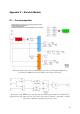
D.1 – The relay algorithm
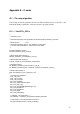
This is the main model, notice the ADC block in red, the green Digital Output block
controlling the LEDs and the twin DFTs coloured blue and orange.
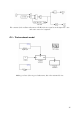
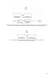
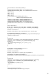
The interior of the DFT blocks, expecting sine and cosine signals from the oscillator block
depicted below. The input signal is converted to the frequency domain – outputting a complex
signal whose amplitude and phase trigger the relays.