
User`s guide


28
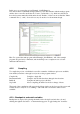
A lot of options regarding the control
logic and deadband are also available –
giving the user full control over how the
resulting signal should behave. Due to
the nature of the application featured in
this report, this has not been thoroughly
investigated.
Note: All inputs to the PWM-block must
be scalar values.
The Timer-block is a useful tool, be it for
triggering a time dependent task or to
check the time taken to execute a task (as
can be seen in the benchmarking chapter
of this report.
One clock cycle is 1.706µs.
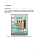
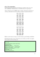
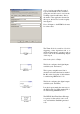
This block configures the digital inputs
available (read: the buttons)
This is pretty straightforward, but it
should be noted that the buttons marked
B1-B3 on the front plate of the hardware
is called using GPIOA bit 15-13.
This block configures the digital outputs
available (read: the LEDs)
It works in pretty much the same way as
the DI-block above. LEDs marked D1-3
are called using GPIOB bit 15-13.
The RTDX, Real Time Data eXchange,
is a great tool that sadly doesn’t work
very well with the Simulink-generated
code.