
User`s guide


27
Appendix B – Simulink blocks
This part of the guide covers some of the new Simulink blocks and how to use them. Basic
knowledge of Simulink and MATLAB is assumed and highly recommended.
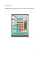
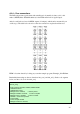
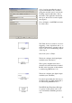
The ADC-block handles the setup of
which inputs should have analog-to-
digital conversion activated.
The user can set sample time as well as
the prefered data type to output. There’s
also options for which modules to
initiate; A and/or B as well as whether
these should be read sequentially or at
the same time.
The number of inputs can be set between
1 and 16 although the block will mux
them together when outputting them so
the user will have to connect a demuxer
when routing the signal.
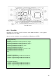
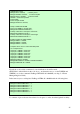
Unlike CCS, setting up a PWM in
Simulink is incredibly easy. The PWM-
block offers a lot of options – for
instance which Event Manager module to
use, the waveform period, whether or not
the waveform should be asymmetric and
of course, which outputs to enable.