
User`s guide


25
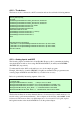
// Initalize EVA Timer2
EvaRegs.T2PR = 0x03FF; // Timer2 period
EvaRegs.T2CMPR = 0x03C0; // Timer2 compare
EvaRegs.T2CNT = 0x0000; // Timer2 counter
// TMODE = continuous up/down
// Timer enable
// Timer compare enable
EvaRegs.T2CON.all = 0x1042;
// Setup T1PWM and T2PWM
// Drive T1/T2 PWM by compare logic
EvaRegs.GPTCONA.bit.TCMPOE = 1;
// Polarity of GP Timer 1 Compare = Active low
EvaRegs.GPTCONA.bit.T1PIN = 1;
// Polarity of GP Timer 2 Compare = Active high
EvaRegs.GPTCONA.bit.T2PIN = 3;
// Enable compare for PWM1-PWM6
EvaRegs.CMPR1 = 0x0C00;
EvaRegs.CMPR2 = 0x3C00;
EvaRegs.CMPR3 = 0xFC00;
// Compare action control. Action that takes place
// on a compare event
// output pin 1 CMPR1 - active high
// output pin 2 CMPR1 - active low
// output pin 3 CMPR2 - active high
// output pin 4 CMPR2 - active low
// output pin 5 CMPR3 - active high
// output pin 6 CMPR3 - active low
EvaRegs.ACTRA.all = 0x0666;
EvaRegs.DBTCONA.all = 0x0000; // Disable deadband
EvaRegs.COMCONA.all = 0xA600;
}
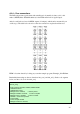
Even if the code is richly commented, some clarifications should be made.
GPTCONA is called bitwise in the code above - an alternative way to set the T1PWM and
T2PWM is to use the command: EvaRegs.GPTCONA.all = 0x0049 (see chap. 5 of Event
Manager Register Guide)
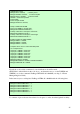
In the same way we could replace EvaRegs.ACTRA.all = 0x0666 with the following lines:
EvaRegs.ACTRA.bit.CMP1ACT1 = 1;
EvaRegs.ACTRA.bit.CMP2ACT0 = 1;
EvaRegs.ACTRA.bit.CMP3ACT1 = 1;
EvaRegs.ACTRA.bit.CMP4ACT0 = 1;
EvaRegs.ACTRA.bit.CMP5ACT1 = 1;
EvaRegs.ACTRA.bit.CMP6ACT0 = 1;
It’s a matter of personal taste since what is lost in space is on the other hand gained in clarity.