
User`s guide


24
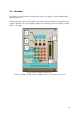
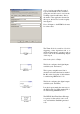
A.3.4 – Rear connections
The DSP can generate a pulse train with variable period (actually, its duty cycle) - this
method, PWM (Pulse-Width Modulation) is the DSPs main form of signal output.
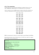
At the boards back, we have 24 PWM outputs (12 unique), which can be measured by an
oscilloscope. The table below show how the rear connections are placed and denoted.
Rear connections
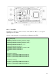
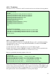
PWM is best introduced by looking at yet another sample program, Example_281xEvPwm.
Particularly interesting are the two functions init_eva() and init_evb(). In the code segment
below, we take a closer look at init_eva()
void init_eva()
{
// EVA Configure T1PWM, T2PWM, PWM1-PWM6
// Initalize the timers
// Initalize EVA Timer1
EvaRegs.T1PR = 0x0FFF; // Timer1 period
EvaRegs.T1CMPR = 0x3C00; // Timer1 compare
EvaRegs.T1CNT = 0x0000; // Timer1 counter
// TMODE = continuous up/down
// Timer enable
// Timer compare enable
EvaRegs.T1CON.all = 0x1042;