
User`s guide

12
5.2 – The model
To check the suitability of the DSP regarding power electronic applications, a simplified relay
model is constructed. The model contains two DFT-algorithms for signal analysis which is
sufficient for detecting both phase anomalies and amplitude changes.
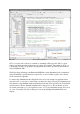
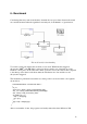
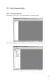
The model of the implemented relay
A more detailed view of the model as well as the generated C-code can be found in
appendixes D and E. To be able to properly handle three-phase currents, a third DFT should
be added – but since the really important question is if the software is capable, or not, of
reproducing the model in functional C-code only two DFTs are displayed for improved
clarity.
The reader should take the opportunity to note the “F2812 eZdsp”-block, in the lower right
corner, containing the target preferences for the DSP.
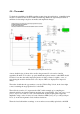
The red block (numbered 1) represents the ADC, in this example we’re sampling two
channels and these are demuxed and rerouted into two separate DFTs. (blue and orange in the
picture, depicted by numbers 2 and 3) From the DFTs we may acquire phase angle and
amplitude, using a series of relays we control the three LEDs (using the green Digital Input
block, 4) on the development board to indicate deviations.
The model was built with no warnings or errors and was successfully uploaded to the DSP.