
User`s guide


8
Each event manager is equipped with two independent timers – making it a total of four.
Timers are useful when handling time critical algorithms or adding delays. The timer works
more or less like an “egg clock”, where the timer counts either up or down with a 16-bit value
(which can be defined by the user) and causes an interrupt at a user-specified value.
Also available to each event manager is eight PWM waveforms. They can be generated
simultaneously, six of them as three independent pairs with programmable deadbands. The
DSP outputs PWM signals between [0, 3.3] V – but thanks to a custom built interface card,
the PWM levels are converted to [-15, 15] V instead.
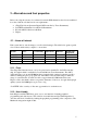
The board is equipped with 16 analog-to-digital conversion-channels. Each channel has a 12-
bit resolution and a 80 ns conversion delay. The maximum sampling frequency is thus 25
MHz. The input signal must be between [0, 3] V. However, the development board available
at the department is equipped with a custom built interface card making it possible to input
signals in the [-10, 10] V range. Users should note that the digital value is aquired using the
following formula:
⎟
⎠
⎞
⎜
⎝
⎛
−
×=
3
log
4095
ADCLOInputAna
ueDigitalVal
ADCLO is marked GND on the front plate.
Common registers and short explanation of their uses can be found in Appendix C.