
User`s guide
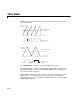
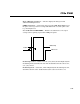
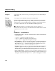
Table Of Contents
- Getting Started
- Using the IQmath Library
- Block Reference
- Blocks — Alphabetical List
- Absolute IQN
- Arctangent IQN
- C24x ADC
- C24x CAN Receive
- C24x CAN Transmit
- C24x From Memory
- C24x PWM
- C24x To Memory
- C28x ADC
- C28x eCAN Receive
- C28x eCAN Transmit
- C28x From Memory
- C28x PWM
- C28x To Memory
- Division IQN
- F2812 eZdsp
- Float to IQN
- Fractional part IQN
- Fractional part IQN x int32
- Integer part IQN
- Integer part IQN x int32
- IQN to Float
- IQN x int32
- IQN x IQN
- IQN1 to IQN2
- IQN1 x IQN2
- LF2407 eZdsp
- Magnitude IQN
- Saturate IQN
- Square Root IQN
- Trig Fcn IQN
- Index

C28x PWM
3-29
3C28x PWM
Purpose Generate code that configures the event manager (EV) modules to generate
PWM waveforms
Library c2800dspchiplib in Embedded Target for TI C2000 DSP
Description F2812 DSPs include a suite of pulse width modulators (PWM) used to generate
various signals. This block provides options to set the A or B module event
managers to generate the waveforms you require. The twelve PWMs are
configured in six pairs, with three pairs in each module.
Module — Specifies which target PWM pairs to use:
•
A — Displays the PWMs in module A (PWM1/PWM2, PWM3/PWM4, and
PWM5/PWM6)
•
B — Displays the PWMs in module B (PWM7/PWM8, PWM9/PWM10, and
PWM11/PWM12)
Note PWMs in module A use the Event Manager A, Timer 1, and PWMs in
module B use Event Manager B, Timer 3. You should make sure that the
TimerClock selected in the Scheduling section of the F2812 eZdsp Target
Preferences block does not conflict with the timers used for the PWMs.
Waveform period source — Source from which the waveform period value is
obtained. Select
Specify via dialog to enter the value in Waveform period or
select
Input port to use a value from the input port.
Waveform period — Period of the timer used to generate the PWM waveform
measured in clock cycles. The relationship betwen the timer period and the
waveform period depends on the
Waveform type.
Note Clock cycles refers to the system CPU clock on the F2812 chip. This
clock is 150 MHz.
Waveform type — Type of waveform to be generated by the PWM pair. The
F2812 PWMs can generate two types of waveforms:
Asymmetric and
C28x PWM
C28x PWM