
User`s guide
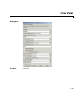
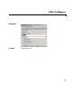
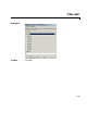
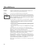
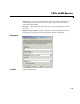
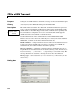
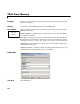
Table Of Contents
- Getting Started
- Using the IQmath Library
- Block Reference
- Blocks — Alphabetical List
- Absolute IQN
- Arctangent IQN
- C24x ADC
- C24x CAN Receive
- C24x CAN Transmit
- C24x From Memory
- C24x PWM
- C24x To Memory
- C28x ADC
- C28x eCAN Receive
- C28x eCAN Transmit
- C28x From Memory
- C28x PWM
- C28x To Memory
- Division IQN
- F2812 eZdsp
- Float to IQN
- Fractional part IQN
- Fractional part IQN x int32
- Integer part IQN
- Integer part IQN x int32
- IQN to Float
- IQN x int32
- IQN x IQN
- IQN1 to IQN2
- IQN1 x IQN2
- LF2407 eZdsp
- Magnitude IQN
- Saturate IQN
- Square Root IQN
- Trig Fcn IQN
- Index

C28x ADC
3-22
3C28x ADC
Purpose Generate code to configure the ADC to output data streams
Library c2800dspchiplib in Embedded Target for TI C2000 DSP
Description The C28x ADC block configures the C28x ADC to perform analog-to-digital
conversion of signals connected to the selected ADC input pins. It outputs
digital values reprensenting the analog input signal and stores the converted
values in the result register of your digital signal processor. You use this block
to capture and digitize analog signals from external sources such as signal
generators, frequency generators, or audio devices.
The output of the C28x ADC is a vector of
uint16 values. The output values
are in the range 0 to 4095 because the C28x ADC is 12-bit converter.
The C28x ADC blcok supports ADC operation in dual-sequencer and
cascaded-sequencer modes. In dual-sequencer mode, either
Module A or
Module B can be used for the ADC block, and two ADC blocks are allowed in
the model. In cascaded-sequencer mode, both
Module A and Module B are
used for a single ADC block.
Module — Specifies which DSP module to use
•
A — Displays the ADC channels in module A (ADCINA0 through
ADCINA7)
•
B — Displays the ADC channels in module B (ADCINB0 through
ADCINB7)
•
A and B — Displays the ADC channels in both modules A and B (ADCINA0
through ADCINA7 and ADCINB0 through ADCINB7)
Use the check boxes to select the desired ADC channels.
Sample time — Time in seconds between consecutive sets of samples that are
converted for the selected ADC channel(s). This is the rate at which values are
read from the result registers. See “Scheduling and Timing” on page 1-8 for
additional information on timing.
To set different sample times for different groups of ADC channels, you must
add separate C28x ADC blocks to your model and set the desired sample times
for each block.
C28x ADC
C28x ADC