
User`s guide

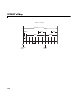
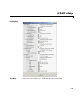
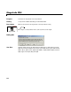
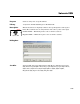
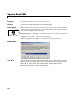
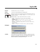

Table Of Contents
- Getting Started
- Using the IQmath Library
- Block Reference
- Blocks — Alphabetical List
- Absolute IQN
- Arctangent IQN
- C24x ADC
- C24x CAN Receive
- C24x CAN Transmit
- C24x From Memory
- C24x PWM
- C24x To Memory
- C28x ADC
- C28x eCAN Receive
- C28x eCAN Transmit
- C28x From Memory
- C28x PWM
- C28x To Memory
- Division IQN
- F2812 eZdsp
- Float to IQN
- Fractional part IQN
- Fractional part IQN x int32
- Integer part IQN
- Integer part IQN x int32
- IQN to Float
- IQN x int32
- IQN x IQN
- IQN1 to IQN2
- IQN1 x IQN2
- LF2407 eZdsp
- Magnitude IQN
- Saturate IQN
- Square Root IQN
- Trig Fcn IQN
- Index

LF2407 eZdsp
3-59
and twice before at a distance of TQ/2. A majority decision is made from
the three points.
SBG — Sets the message resynchronization triggering. Options are
Only_falling_edges and Both_falling_and_rising_edges.
SJW — Sets the synchronization jump width, which determines how many
units of TQ a bit is allowed to be shortened or lengthened when
resynchronizing.
SelfTestMode — If True, sets the CAN module to loopback mode, where a
“dummy” acknowledge message is sent back without needing an
acknowledge bit.
TSEG1 — Sets the value of time segment 1, which, with TSEG2 and BRP,
determines the length of a bit on the CAN bus. TSEG1 must be greater
than TSEG2 and the Information Processing Time (IPT). The IPT is the
time needed to process one bit and corresponds to two TQ units.
TSEG1 = PROP_SEG + PHASE_SEG1. Valid values for TSEG1 are from
1 through 16.
TSEG2 — Sets the value of time segment 2 (PHASE_SEG2), which, with
TSEG1 and BRP, determines the length of a bit on the CAN bus. TSEG2
must be less than or equal to TSEG1 and greater than or equal to IPT.
Valid values for TSEG2 are from 1 through 8.
-
DSP Chip Label — DSP chip model. Select the DSP chip installed on your
target. The chip model is fixed for the LF2407 eZdsp. If you change the
chip model, an error will be generated in code generation.
The CAN bit timing is shown in the following illustration.