
User guide


98 www.xilinx.com System Generator for DSP User Guide
UG640 (v 12.2) July 23, 2010
Chapter 1: Hardware Design Using System Generator
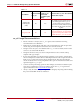
ce_clr Usage Recommendations
• Based on the above analysis, the ce_clr signal can be used if the following
recommendations are adhered to:
• Replace down sampler blocks with first value of frame behavior with an equivalent
circuit using down sampler block with last value of frame selected.
• Design for N clock cycles of invalid data after ce_clr is de-asserted, where N is the
slowest ce associated with the block.
• Design the model to always use down sampler with last value of frame and up
sampler with copy samples.
• If N cycle invalid data is not desired replace parallel to serial, serial to parallel, time
division multiplexer and time division demultiplexer block with an equivalent circuit
built out of a counter, mux and up/down sampler blocks. The equivalent design
circuit should also have a reset port pulled to the top-level and connected to the same
signal driving the ce_clr port.
• Counters used in performing operations like multiply-accumulate should always be
reset using a combination of user reset which is tied to the ce_clr signal and ce
signal extracted from the Clock Enable Probe
block.
• Always verify the effect of ce_clr signal on the design by importing and simulating
the post translate HDL model as a black box.
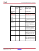
Addressable
Shift Register
(ASR)
No Yes
The ASR block will hold the values in
the shift register when ce_clr is
asserted. When de-asserted, the
stored values will be shifted out, and
new data will be put into the shift
register.
Polyphase FIR No No
Interpolating or Decimating FIR does
not work with the ce_clr signal unless
the optional reset port is used to reset
the FIR after the ce_clr is de-asserted.
Table 1-1:
Block Name
Synchronized
to ce_clr
Synchronized to
ce after ce_clr
deasserted
( 1 sample cycle
delay)
Behavior after ce_clr is de-asserted
and the next ce pulse