
User guide

90 www.xilinx.com System Generator for DSP User Guide
UG640 (v 12.2) July 23, 2010
Chapter 1: Hardware Design Using System Generator
Reduce the Clock Enable (CE) Fanout
An algorithm in the ISE® Mapper uses register duplication and placement based on
recursive partitioning of loads on high fanout nets. This means improved FMAX on
System Generator designs with large CE fanout.
Although this feature is enabled in System Generator by default, the fanout reduction
occurs downstream during the ISE mapping operation and the following MAP options
must be turned on:
• Perform Timing-Driven Packing and Placement : on
• Map Effort Level : High
• Register Duplication : on
If you are using the ISE Project Navigator flow, these MAP options are also on by default.
However, if you are using a System Generator flow like Bitstream, you must turn on these
MAP options by modifying the bitstream .opt file or by providing you own .opt file. See
the topic XFLOW Option Files for more information.
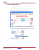
Processing a System Generator Design with FPGA Physical
Design Tools
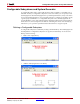
HDL Simulation
System Generator creates custom .do files for use with your generated project and a
ModelSim simulator. To use these files, you must have ModelSim. You may run your
simulations from the standalone ModelSim tool, or you may associate it with the Xilinx
ISE® Project Navigator, and run your simulations from within Project Navigator as part of
the full software implementation flow.
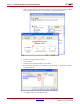
Compiling Your IP
Before you can simulate your design, you must compile your IP (cores) libraries with
ModelSim.
ModelSim SE
There are multiple ways to compile your IP libraries. Complete instructions for running
compxlib can be found in the chapter titled COMPXLIB in the Command Line Tools User
Guide.
From the Windows command line you can compile the necessary HDL libraries using the
compxlib program. For example, the following command can be used to compile all the
HDL libraries with ModelSim SE:
compxlib -s mti_se -f all -l all