
User guide

System Generator for DSP User Guide www.xilinx.com 89
UG640 (v 12.2) July 23, 2010
Notes for Higher Performance FPGA Design
Notes for Higher Performance FPGA Design
When you use the following design practices, it helps System Generator produce efficient
and high performance hardware realizations.
Review the Hardware Notes Included in Block Dialog Boxes
Pay close attention to the Hardware Notes included in the block dialog boxes. Many blocks
in the Xilinx Blockset library have notes that explain how to achieve the most hardware
efficient implementation. For example, the notes point out that the Scale block costs
nothing in hardware. By contrast, the Shift block (which is sometimes used for the same
purpose) can use hardware.
Register the Inputs and Outputs of Your Design
Register inputs and outputs of your design. This can be done by placing a Delay block
having latency 1 or a Register block after the Gateway In and before Gateway Out blocks.
Selecting any of the Register block features adds hardware.
Double registering the I/Os may also be beneficial. This can be performed by instantiating
two separate Register blocks, or by instantiating two Delay blocks, each having latency 1.
This allows one of the registers to be packed into the IOB and the other to be placed next to
the logic in the FPGA fabric. A Delay block with latency 2 does not give the same result
since this block is implemented using an SRL16 and cannot be packed into an IOB.
Insert Pipeline Registers
Insert pipeline registers wherever possible. Deep pipelines are efficiently implemented
with the Delay blocks since the SRL16 primitive is used. If an initial value is needed on a
register, the Register block should be used.
Use Saturation Arithmetic and Rounding Only When Necessary
Saturation arithmetic and rounding have area and performance costs. Use only if
necessary.
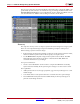
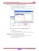
Use the System Generator Timing and Power Analysis Tools
You can use System Generator Timing and Power Analysis Tools to Meet Timing
Requirements. System Generator provides a Timing Analysis tool that can help resolve
timing related issues. The timing analysis tool shows you the slowest paths and those
paths which are failing to meet the timing requirements. The power analysis tool XPower
can be used to provide a quick, less accurate analysis or a complete analysis using a full
HDL simulation run. For more information, refer to topic Timing and Power Analysis
Compilation.
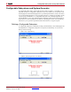
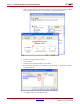
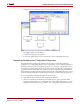
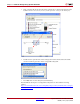
Set the Data Rate Option on All Gateway Blocks
Select the IOB timing constraint option Data Rate on all Gateway In and Gateway Out
blocks. When Data Rate is selected, the IOBs are constrained at the data rate at which the
IOBs operate. The rate is determined by the Simulink system period(sec) field in the
System Generator block and the sample rate of the Gateway relative to the other sample
periods in the design.