
User guide

82 www.xilinx.com System Generator for DSP User Guide
UG640 (v 12.2) July 23, 2010
Chapter 1: Hardware Design Using System Generator
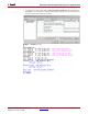
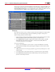
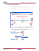
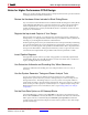
The previous screen shot shows the ModelSim commands used to compile the VHDL code
generated by System Generator. To simulate the top_level design, double left click on the
Simulate Behavioral Model process. The ModelSim .do file compiles the VHDL code and
runs the simulation for 10000 ns. The resulting waveform is shown below.
Summary
This topic has shown you how to import a System Generator Design into a larger system.
There are a few important things to keep in mind during each phase of the process.
While creating a System Generator design:
• IOB constraints should not be specified on Gateways in the System Generator model;
neither should the System Generator block specify a clock pin location.
• Use the HDL Netlist compilation target in the System Generator block. The HDL
Netlist file that System Generator produces contains both the RTL, EDIF and
constraint information for your design.
For top-level simulation:
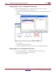
• Create a custom ModelSim .do file in order to compile the VHDL files created by
System Generator. Modify the Project Navigator settings to use this custom .do file
New capabilities:
• Add System Generator Source type project file (.sgp) into Project Navigator as a sub-
module design
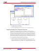
• Consolidate and associate System Generator constraints into the top-level design
• Launch MATLAB and System Generator MDL directly from Project Navigator to
perform certain design iterations