
User guide

System Generator for DSP User Guide www.xilinx.com 79
UG640 (v 12.2) July 23, 2010
Importing a System Generator Design into a Bigger System
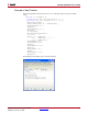
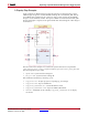
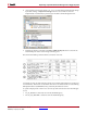
4. As shown below, make sure the file top_level is selected, then implement the design
by double clicking on Implement Design in the Processes window. Once the
implementation is finished, Project Navigator should look like the figure below.
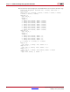
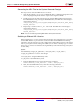
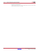
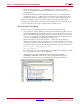
5. Examine the timing constraints in the Place and Route Report that is located in the
Detailed Reports section of the Design Summery pane.
Note that in the PAR report the multirate constraints were met:
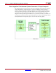
Constraints for each System Generator design were created and translated to a UCF (User
Constraint File). These UCF constraint files were then consolidated and associated during
ISE implementation (NGDBUILD). They are briefly described as follows:
A system sample period of 100 ns was set in the System Generator block for both designs
(1 & 2)
• TS_clk_f488215c2 constraints are from the SRAM design (1)
• The TS_clk_c4b7e2441 constraints are from the FIR design (2)