
User guide

System Generator for DSP User Guide www.xilinx.com 49
UG640 (v 12.2) July 23, 2010
Automatic Code Generation
added to a larger design, but the clock wrapper is omitted. In this case, you are responsible
for generating clocks and clock enables, but a finer degree of control is obtained. If, on the
other hand, the clock wrapper is suitable for the application, then include it.
The names of the clocks and clock enables in System Generator HDL suggest that clocking
is completely general, but this is not the case. To illustrate this, assume a design has clocks
named clk_1 and clk_2, and companion clock enables named ce_1 and ce_2 respectively.
You might expect that working hardware could be produced if the ce_1 and ce_2 signals
were tied high, and clk_2 were driven by a clock signal whose rate is half that of clk_1. For
most System Generator designs this does not work. Instead, clk_1 and clk_2 must be driven
by the same clock, ce_1 must be tied high, and ce_2 must vary at a rate half that of clk_1 and
clk_2.
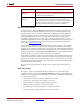
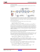
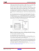
The clock wrapper consists of two components: one for the design itself, and one clock
driver component that generate clocks and clock enables. The clock driver is contained in a
file named <design>_cw.vhd/.v. The logic within the <design>_cw generates the
ce_x signals. The optional ce_clr port would be generated if the design was generated
by selecting Provide clock enable clear pin on the System Generator block. The ports that
are not clocks or clock enables are passed through to the exterior of the clock wrapper.
Schematically, the clock wrapper looks like the diagram below.
Note:
The clock wrapper exposes a port named ce. The port does nothing except to serve as a
companion to the clk port on the wrapper. The reason for having the port is to allow the clock wrapper
to be used as a black box in System Generator designs.
The “Hybrid DCM-CE” Multirate Implementation
If the implementation target is an FPGA with a Digital Clock Manager (DCM), you can
choose to drive the clock tree with a DCM. The DCM option is desirable when high fanout
on clock enable nets make it difficult to achieve timing closure.
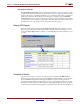
System Generator instantiates the DCM in a top-level HDL clock wrapper ( with a suffix
_dcm_mcw) and configures the DCM to provide up to
three clock ports at different rates for
Virtex®-4 and Virtex®-5 and up to two clock ports for Spartan-3A DSP
. If the design has more
clock ports than the DCM can support, the remaining clocks are supported with the CE
(clock enable) configuration as described in the previous topic.
For a detailed examination of the files produced by this option, refer to the topic Tutorial
Example: Using the Hybrid DCM-CE Option.