
User guide

46 www.xilinx.com System Generator for DSP User Guide
UG640 (v 12.2) July 23, 2010
Chapter 1: Hardware Design Using System Generator
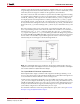
Using the System Generator Constraints File
When a design is compiled, System Generator produces a constraints file that tells
downstream tools how to process the design. This enables the tools to produce a higher
quality implementation, and to do so using considerably less time. Constraints supply the
following:
• The period to be used for the system clock;
• The speed, with respect to the system clock, at which various portions of the design
must run;
• The pin locations at which ports should be placed;
• The speed at which ports must operate.
The file format depends on the synthesis tool that is specified in the System Generator
block. When XST is selected, the file is written in the XCF format; for Synplify and Synplify
Pro, the NCF format is used. The file name ends with.xcf or .ncf, as appropriate.
System Clock Period
The system clock period (i.e., the period of the fastest hardware clock in the design) can be
specified in the System Generator block. System Generator writes this period to the
constraints file. Downstream tools use the period as a goal when implementing the design.
Multicycle Path Constraints
Many designs consist of parts that run at different clock rates. For the fastest part, the
system clock period is used. For the remaining parts, the clock period is an integer multiple
of the system clock period. It is important that downstream tools know what speed each
part of the design must achieve. With this information, efficiency and effectiveness of the
tools are greatly increased, resulting in reduced compilation times and improved
hardware realizations. The division of the design into parts, and the speed at which each
part must run, are specified in the constraints file using multicycle path constraints.
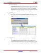
IOB Timing and Placement Constraints
When translated into hardware, System Generator's Gateway In and Gateway Out blocks
become input and output ports. The locations of these ports and the speeds at which they
must operate can be entered in the Gateway In and Out parameter dialog boxes.
See the descriptions of the Gateway In
block and the Gateway Out block for more
information. Port location and speed are specified in the constraints file by IOB timing.