
User guide

System Generator for DSP User Guide www.xilinx.com 43
UG640 (v 12.2) July 23, 2010
Automatic Code Generation
Simulink System Period
You must specify a value for Simulink system period in the System Generator block
dialog box. This value tells the underlying rate, in seconds, at which simulations of the
design should run. The period must evenly divide all sample periods in the design. For
example, if the design consists of blocks whose sample periods are 2, 6, and 8, then the
largest acceptable sample period is 2, though other values such as 1 and 0.5 are also
acceptable. Sample periods arise in three ways: some are specified explicitly, some are
calculated automatically, and some arise implicitly within blocks that involve internal rate
changes. For more information on how the system period setting affects the hardware
clock, refer to Timing and Clocking
.
Before running a simulation or compiling the design, System Generator verifies that the
period evenly divides every sample period in the design. If a problem is found, System
Generator opens a dialog box suggesting an appropriate value. Clicking the button labeled
Update instructs System Generator to use the suggested value. To see a summary of period
conflicts, click the button labeled View Conflict Summary. If you allow System Generator
to update the period, you must restart the simulation or compilation.
It is possible to assemble a System Generator model that is inconsistent because its periods
cannot be reconciled. (For example, certain blocks require that they run at the system rate.
Driving an up-sampler with such a block produces an inconsistent model.) If, even after
updating the system period, System Generator reports there are conflicts, then the model is
inconsistent and must be corrected.
The period control is hierarchical; see the discussion of hierarchical controls below for
details.
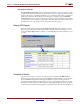
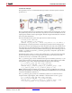
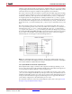
Block Icon Display
The options on this control affect the display of the block icons on the model. After
compilation (which occurs when Generating, Simulating, or by pressing Control-D) of
the model various information about the block in your model can be displayed, depending
on which option is chosen.
• Default—basic information about port directions are shown
• Sample rates—the sample rates of each port are shown
• Pipeline stages—the number of pipeline stages are shown
• HDL port names—the names of the ports are shown
• Input data types—the input data types for each port are shown
• Output data types—output data types for each port are shown
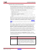
DCM input clock
period(ns)
Specify if different than the FPGA clock period(ns) option (system
clock). The FPGA clock period (system clock) will then be derived
from this hardware-defined input.
Provide clock enable
clear pin
This instructs System Generator to provide a ce_clr port on the top-
level clock wrapper. The ce_clr signal is used to reset the clock
enable generation logic. Capability to reset clock enable generations
logic allows designs to have dynamic control for specifying the
beginning of data path sampling. See the topic for details.
Control Description