
User guide

42 www.xilinx.com System Generator for DSP User Guide
UG640 (v 12.2) July 23, 2010
Chapter 1: Hardware Design Using System Generator
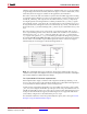
Synthesis tool Specifies the tool to be used to synthesize the design. The
possibilities are Synplify, Synplify Pro and Xilinx XST.
Hardware description
language
Specifies the language to be used for HDL netlist of the design. The
possibilities are VHDL and Verilog.
Create testbench This instructs System Generator to create an HDL testbench.
Simulating the testbench in an HDL simulator compares Simulink
simulation results with ones obtained from the compiled version of
the design. To construct test vectors, System Generator simulates the
design in Simulink, and saves the values seen at gateways. The top
HDL file for the testbench is named <name>_testbench.vhd/.v,
where <name> is a name derived from the portion of the design
being tested and the extension is dependent on the hardware
description language.
Import as
configurable
subsystem
Tells System Generator to do two things: 1) Construct a block to
which the results of compilation are associated, and 2) Construct a
configurable subsystem consisting of the block and the original
subsystem from which the block was derived. See Configurable
Subsystems and System Generator for details.
FPGA clock period
Defines the period in nanoseconds of the system clock. The value
need not be an integer. The period is passed to the Xilinx
implementation tools through a constraints file, where it is used as
the global PERIOD constraint. Multicycle paths are constrained to
integer multiples of this value.
Clock pin location Defines the pin location for the hardware clock. This information is
passed to the Xilinx implementation tools through a constraints file.
Multirate
implementation
Clock Enables (default): Creates a clock enable generator circuit to
drive a multirate design.
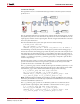
Hybrid DCM-CE: Creates a clock wrapper with a DCM that can
drive up to three clock ports at different rates for Virtex®-4 and
Virtex®-5 and up to two clock ports for Spartan-3A DSP. The
mapping of rates to the DCM output ports is done using the
following priority scheme: CLK0 > CLK2x > CLKdv > CLKfx. The
DCM honors the higher clock rates first. If the design contains more
clocks than the DCM can handle, the remaining clocks are
implemented using the Clock Enable configuration.
A reset input port is exposed on the DCM clock wrapper to allow
resetting the DCM and a locked output port is exposed to help the
external design synchronize the input data with the single clk
input pin.
Expose Clock Ports: This option exposes multiple clock ports on the
top-level of the System Generator design so you can apply multiple
synchronous clock inputs from outside the design.
Control Description