
User guide

System Generator for DSP User Guide www.xilinx.com 399
UG640 (v 12.2) July 23, 2010
Timing and Power Analysis Compilation
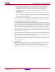
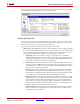
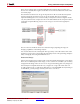
There are two failing paths, normally highlighted in red/pink. (The top path is gray
because it is selected.) The negative slack values are shown in boldface. The worst of the
two fails by 96ps.
Note that there are two levels of logic in the path shown. How can this be? The System
Generator diagram shows three levels of logic in all paths. The reason is that the
implemented design does not correlate exactly to the System Generator diagram. In this
case, the synthesizer has compressed some of the 2-bit XOR blocks into 4-input LUTs and
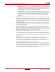
created the 8-input XOR using only two levels of logic as shown in this Synplify Pro
schematic:
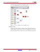
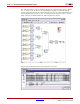
Note how the net and block names have all been munged, requiring the magic un-
munging capabilities of the timing analyzer.
Also note the details of the selected path. The logic delays cannot be reduced. One of the
net delays is 813ps. This could possibly be reduced by means of floorplanning, multipass
PAR, or simply by increasing the PAR effort level.
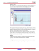
Rescue the Design
Instead, let us attempt a more robust solution to fix the path by changing the source design.
There are no feedback paths in this design, so let us assume we can add a cycle of latency
and pipeline the design. There are two levels of logic in the failing paths. Any design can
theoretically be re-implemented with only a single level of logic. We will do this now.
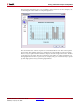
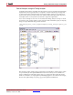
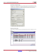
To add a pipeline stage, we will merely add latency to selected XOR blocks. By clicking on
an XOR block, you may change its latency from zero to one like so: