
User guide

388 www.xilinx.com System Generator for DSP User Guide
UG640 (v 12.2) July 23, 2010
Chapter 5: System Generator Compilation Types
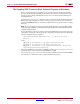
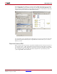
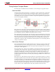
After filling out the dialog box, click the Generate button and System Generator will
perform the following steps:
1. The design is compiled using Simulink then netlisted by Sysgen into HDL source.
2. If you selected the Power Analysis option Full simulation-based analysis, the ISim
simulator is called to simulate the HDL design. The HDL Synthesis Tool is then called
to turn the HDL into an EDIF (Synplify/Synplify Pro) or NGC (XST) netlist.
3. NGD Build is called to next to turn the netlist into an NGD file. The ISE Mapper
software is then called to map elements of logic together into slices; this creates an
NCD file.
4. The ISE Place & Route software is then called to place the slices and other elements on
the Xilinx die and to route the connections between the slices. This creates another
NCD file.
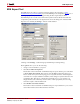
5. The ISE Trace software is then called to analyze the second NCD file and find the paths
with the worst slack. This creates a trace report. The System Generator Timing
Analyzer tool appears, displaying the data from the trace report.
Note:
If timing data is generated using this method and you wish to view it again at a later time, then
you can enter the following command at the MATLAB command line:
>>xlTimingAnalysis('timing')
where 'timing' is the name of the target directory in which a prior analysis was carried out.
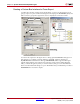
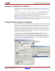
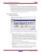
6. As shown below, you can click the Power Analysis button on the Timing Analyzer
window to bring up the Xilinx XPower Analysis tool report.
Click