
User guide

System Generator for DSP User Guide www.xilinx.com 369
UG640 (v 12.2) July 23, 2010
Black Box Examples
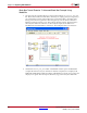
8. Once the number of input ports is determined, the M-function adds the input ports to
the black box. The code that does this is shown below.
for i=1:nports
this_block.addSimulinkInport(sprintf('sig%d',i));
end
There are four VHDL files, named scope1.vhd, scope2.vhd, scope3.vhd, and
scope4.vhd, which the black box in this example can use. The black box associates
itself to the one that declares an appropriate number of ports.
9. The configuration M-function selects the appropriate VHDL file for the black box.
Locate the following line in scope_config.m:
entityName = sprintf('scope%d',nports);
The HDL entity name for the black box is constructed by appending the value of
nports to scope. The VHDL is associated with the black box in the following line:
this_block.addFile(['vhdl/' entityName '.vhd']);
10. The input port widths for each VHDL entity are assigned using generics. The generic
name identifies the input port to which the width is assigned. For example, the width3
generic specifies the width of the third input. In scope_config.m, the generic names
and values are set as follows:
% -----------------------------
if (this_block.inputTypesKnown)
for i=1:nports
width = this_block.inport(i).width;
this_block.addGeneric(sprintf('width%d',i),width);
end
end % if(inputTypesKnown)
% -----------------------------
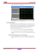
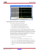
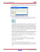
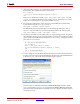
11. You can change the way ModelSim displays the signal waveforms during simulation
by using custom tcl scripts in the ModelSim block. Double click on the ModelSim block
in the black_box_ex5 model. The following dialog box appears:
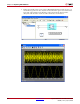
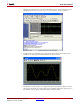
Custom scripts are defined by selecting the Add Custom Scripts checkbox. In this
case, a script named waveform.do is specified in the Script to Run after vsim field.
This script contains the ModelSim commands necessary to display the adder output as
an analog waveform.