
User guide

364 www.xilinx.com System Generator for DSP User Guide
UG640 (v 12.2) July 23, 2010
Chapter 4: Importing HDL Modules
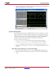
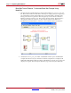
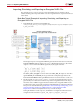
the connection between the black boxes and ModelSim. The example model is shown in
the figure below.
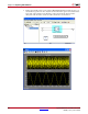
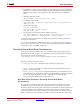
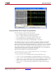
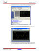
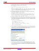
If you run the simulation, you will see a Simulink scope and ModelSim waveform window
that look like the figures below. The scope shows that the black boxes produce matching
parity results (as expected), but with one delayed from the other by one clock cycle. The
waveform window shows the same results, but viewed in ModelSim and expressed in
binary. System Generator automatically configures the waveform viewer to display the
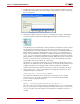
input and output signals of each black box. You can also browse the design structure in
ModelSim to see how System Generator has elaborated the design to combine the two
black boxes.