
User guide

System Generator for DSP User Guide www.xilinx.com 35
UG640 (v 12.2) July 23, 2010
System-Level Modeling in System Generator
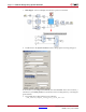
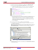
4. Under the Project Navigator Processes view, double-click on Implement Design.
5. From the Project Navigator Design Sources Hierarchy view, do the following:
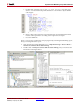
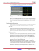
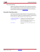
a. Double-click on the file expose_clock_ports_case1_mcw.vhd, then scroll
down to view the entity named expose_clock_ports_mcw, as shown below:
b. Observe that System Generator infers the clocks based on the different rates in the
design and brings the clock ports to the top-level wrapper. Since this design
contains two clock rates, clocks clk_1 and clk_5 are pulled to the top-level
wrapper. This will allow you to directly drive the multiple synchronous clocks
from outside the System Generator design.
c. Close the VHDL file.
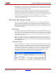
Next you want to perform a behavior simulation using the ModelSim.
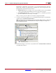
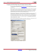
6. As shown below, move to the Sources for dialog box in the Sources window, then
select Behavioral Simulation
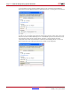
Note:
System Generator automatically creates the top-wrapper VHDL testbench, script file and
input/output stimulus data files. The Processes tab changes and displays according to the
Sources type being selected.
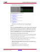
7. Simulate the design, as shown above, by double-click on Simulate Behavioral Model
in the Processes window
2. Double Click
1. Select