
User guide

310 www.xilinx.com System Generator for DSP User Guide
UG640 (v 12.2) July 23, 2010
Chapter 3: Using Hardware Co-Simulation
• Add: Brings up the dialog to enter information about the new port.
• Edit: Make changes to the selected port.
• Delete: Remove the selected port from the list.
Help: Displays this documentation.
Load: Fill in the form with values stored in an SBDBuilder Saved Description XML file.
This file is automatically saved with every plugin that you create, so it is useful for
reloading old plugin files for easy modification.
Save Zip: Prompts you for a filename and a target pathname. This will create a zip file with
all of the plugin files for System Generator. The zip will be in a suitable format for passing
to the System Generator xlInstallPlugin
function.
Exit: Quit the application.
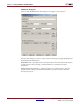
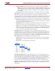
Specifying Non-Memory Mapped Ports
You may use SBDBuilder to specify the non-memory mapped ports for your FPGA board.
When you choose to Add or Edit a non-memory mapped port from the main dialog, the
port editor dialog will come up as shown below.
The port editor dialog presents the following controls for port configuration:
Port Options: Specifies the options that will affect the entire port.
• Port Name: This is the name that will describe the port in System Generator. It should
be a MATLAB-compatible name (begins with a letter, followed by only letters,
numbers, and underscores).
• Input/Output: Specifies the direction of the port.
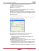
New Pin: This is the entry point to add pins to a port. Ports may consist of a single pin for
a Boolean value, or multiple pins for a vector or bus.
• Pin LOC: Defines the absolute placement of the pin within the FPGA by specifying a
location constraint. It is necessary to define this for every pin to make sure that the
FPGA programming corresponds to the actual hardware connections.
• PULLUP: A constraint that can be applied to each pin. It guarantees a logic High level
to allow 3-stated nets to avoid floating when not being driven.