
User guide

System Generator for DSP User Guide www.xilinx.com 309
UG640 (v 12.2) July 23, 2010
Supporting New Boards through JTAG Hardware Co-Simulation
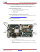
• Frequency (MHz): Specifies the frequency of the on-board system clock in MHz.
Note:
You should use a clock frequency between 10 MHz and 100 MHz. Depending on the
target FPGA device and your design, the design compiled for hardware co-simulation may
not meet timing constraints at a higher clock frequency after the hardware co-simulation
logic is added.
• Pin Location: Specifies the FPGA input pin to which the system clock is connected.
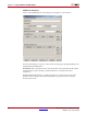
JTAG Options: System Generator needs to know several things about the FPGA board's
JTAG chain to be able to program the FPGA for hardware co-simulation. The topic
Obtaining Platform Information describes how and where to find the information required
for these fields. If you are unsure of the specifications of your board, please refer to the
manufacturer's documentation. The fields specific to JTAG Options are described below:
• Boundary Scan Position: Specifies the position of the target FPGA on the JTAG chain.
This value should be indexed from 1. (e.g. the first device in the chain has an index of
1, the second device has an index of 2, etc.)
• IR Lengths: Specifies the lengths of the instruction registers for all of the devices on
the JTAG chain. This list may be delimited by spaces, commas, or semicolons.
• Detect: This action attempts to identify the IR Lengths automatically by querying the
FPGA board. The board must be powered and connected to a Parallel Cable IV for this
to function properly. Any unknown devices on the JTAG chain will be represented
with a "?" in the list, and must be specified manually.
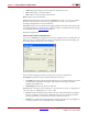
Targetable Devices: This table displays a list of available FPGAs on the board for
programming. This is not a description of all of the devices on the JTAG chain, but rather a
description of the possible devices that may exist at the aforementioned boundary scan
position. For most boards, only one device needs to be specified, but some boards may
have alternate, e.g., a choice between an xcv1000 or an xcv2000 in the same socket. Use the
Add and Delete buttons described below to build the device list:
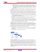
• Add: Brings up a menu to select a new device for the board. As shown in the figure
below, devices are organized by family, then part name, then speed, and finally the
package type.
• Delete: Remove the selected device from the list.
Non-Memory-Mapped Ports: You can add support for your own board-specific ports
when creating a board support package. Board-specific ports are useful when you have on-
board components (e.g., external memories, DACs, or ADCs) that you would like the
FPGA to interface to during hardware co-simulation. Board specific ports are also referred
to as non-memory-mapped because when the design is compiled for hardware co-
simulation, these ports will be mapped to their physical locations, rather than creating
Simulink ports. See Specifying Non-Memory Mapped Ports for more information. The
Add, Edit, and Delete buttons provide the controls needed for configuring non-memory
mapped ports.