
User guide

System Generator for DSP User Guide www.xilinx.com 305
UG640 (v 12.2) July 23, 2010
Installing Your Board for JTAG Hardware Co-Simulation
Installing an SP601/SP605 Board for JTAG Hardware Co-Simulation
The following procedure describes how to install and setup the hardware and software
required to run JTAG Hardware Co-Simulation on an SP601/SP605 board.
Assemble the Required Hardware
1. Xilinx Spartan®-6 SP601/SP605 Kit includes the following:
a. Spartan-6 LXT SP601/SP605 board
b. 12V Power Supply
c. Mini USB cable
Install Xilinx ISE Design Suite Software on the Host PC
Install Xilinx ISE® Design Suite software in the Host PC as described in the document:
ISE Design Suite Installation, Licensing, and Release Notes
Setup the SP601/SP605 Board
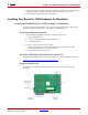
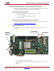
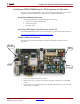
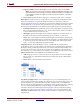
The figure below illustrates the SP605 components of interest in this JTAG setup
procedure:
1. Position the SP605 board as shown above.
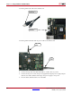
2. Make sure the power switch, located in the right edge of the board, is in the OFF
position.
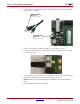
3. As shown below, connect the small end of the Mini USB cable to the connector USB
socket closest to the LEDs.
Power
Connector
LEDs
Power
Switch
Mini USB
Connector