
User guide

304 www.xilinx.com System Generator for DSP User Guide
UG640 (v 12.2) July 23, 2010
Chapter 3: Using Hardware Co-Simulation
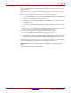
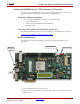
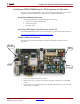
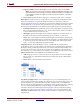
3. As shown below, connect the small end of the Mini USB cable to the connector USB
socket closest to the LEDs.
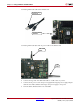
4. Connect the large end of the Mini USB cable to a USB socket on your PC.
As shown below, the LED next to the Mini USB connector turns green when the cable
is connected properly.
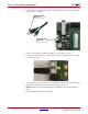
5. Connect the AC power cord to the power supply brick. Plug the power supply adapter
cable into the ML605 board. Plug in the power supply to AC power.
Caution!
Make sure you use an appropriate power supply with correct voltage and power
ratings.
6. Turn the ML605 board Power switch ON.
Connect Large
End to PC
Connect Small
End Here
LED turns green when
the cable is connected
properly