
User guide

302 www.xilinx.com System Generator for DSP User Guide
UG640 (v 12.2) July 23, 2010
Chapter 3: Using Hardware Co-Simulation
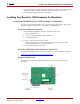
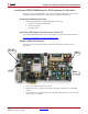
1. Position the ML402 board so the Virtex®-4 and Xilinx logos are oriented near the top
edge of the board.
2. Make sure the power switch, located in the upper-right corner of the board, is in the
OFF position.
3. If you are using a Xilinx Parallel Cable IV, follow steps 3a through 3d.
a. Connect the DB25 Plug Connector on the Xilinx Parallel Cable IV to the IEEE-1284
compliant PC Parallel (Printer) Port Connector.
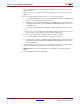
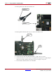
b. Using the narrow (14 pin) 6” High Performance Ribbon cable, connect the pod end
of the Xilinx Parallel Cable IV to the FPGA & CPU Debug Port (shown above) on
the ML402 board.
c. Connect the attached Power Jack cable to the Keyboard/Mouse connector on the
PC.
d. If necessary, connect the male end of the Keyboard/Mouse cable to the associated
female connector on the Xilinx Power Jack cable (splitter cable).
4. If you are using a Xilinx Platform Cable USB, follow step 4a and 4b.
a. Connect the Xilinx Platform Cable USB to a USB port on the PC.
b. Using the narrow (14 pin) 6” High Performance Ribbon cable, connect the pod end
of the Xilinx Platform Cable USB to the FPGA & CPU Debug Port (shown above)
on the ML402 board.
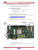
5. Connect the AC power cord to the power supply brick. Plug the power supply adapter
cable into the ML402 board. Plug in the power supply to AC power.
Caution!
Make sure you use an appropriate power supply with correct voltage and power
ratings.
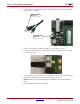
6. Turn the ML402 board Power switch ON.