
User guide

296 www.xilinx.com System Generator for DSP User Guide
UG640 (v 12.2) July 23, 2010
Chapter 3: Using Hardware Co-Simulation
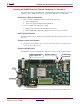
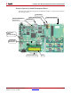
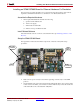
The figure below illustrates the Spartan-3A 3400A Board (Rev D) components of interest in
this setup procedure:
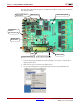
1. Position the Spartan-3A 3400A Development Board as shown above with the LCD
display at the bottom.
2. Make sure the power switch is in the OFF position.
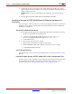
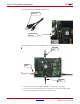
3. As shown below, Eject the CompactFlash card from the CompactFlash Reader.
Ethernet Port
Power Switch
LCD
Configuration
Address
DIP Switches (S2)
Ethernet Mode Select
jumper (JP2)
Compact Flash Card
+5V Power Connector
LYR178-101D (Rev D)
System ACE™
Reset Button