
User guide

294 www.xilinx.com System Generator for DSP User Guide
UG640 (v 12.2) July 23, 2010
Chapter 3: Using Hardware Co-Simulation
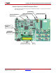
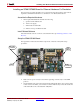
5. Connect the AC power cord to the power supply brick. Plug the 5V power supply
adapter cable into the 5V DC ONLY connector (J5) on the Starter Board. Plug the power
supply cord into AC power.
Caution!
Make sure you use an appropriate power supply with correct voltage and power
ratings.
6. Turn the Spartan-3A DSP 1800A Starter Board POWER switch ON.
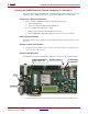
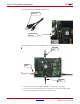
Installing a Spartan-3A DSP 3400A Board for Ethernet Hardware Co-
Simulation
The following procedure describes how to install and configure the hardware and software
required to run an Spartan-3A DSP 3400A Development Board Point-to-Point Ethernet
Hardware Co-Simulation.
Assemble the Required Hardware
1. Xilinx Spartan-3A DSP 3400A Development Board Kit which includes the following:
a. Spartan-3A DSP 3400A Development Board
b. +12V Power Supply bundled with Board LYR178-101C (Rev C) or
+5 V Power Supply bundled with Board LYR178-101D (Rev D)
c. CompactFlash Card
2. You also need the following items on hand:
a. Ethernet network Interface Card (NIC) for the host PC.
b. Ethernet RJ45 Male/Male cable. (May be a Network or Crossover cable.)
c. CompactFlash Reader for the PC.
Install Related Software
Install the related software on the PC as described in the topic Installing Software on the
Host PC.
Load the Sysgen Spartan-3A DSP 3400A HW Co-Sim Configuration Files
System Generator comes with HW Co-Sim configuration files that first need to be loaded
into the Spartan-3A DSP 3400 CompactFlash card. Follow the instructions that are
described in the topic Loading the Sysgen HW Co-Sim Configuration Files.