
User guide

System Generator for DSP User Guide www.xilinx.com 293
UG640 (v 12.2) July 23, 2010
Installing Your Board for Ethernet Hardware Co-Simulation
Installing a Spartan-3A DSP 1800A Starter Board for Ethernet Hardware
Co-Simulation
The following procedure describes how to install and setup the hardware and software
required to run Hardware Co-Simulation on a Spartan-3A DSP 1800A Starter Board. This
board uses a JTAG cable instead of System ACE™ to download the configuration
bitstream.
Assemble the Required Hardware
1. Xilinx Spartan-3A DSP 1800A Starter Board which includes the following:
a. Spartan-3A DSP 1800A Starter Board
b. 5V Power Supply bundled with the development kit
2. You also need the following items on hand:
a. Ethernet network Interface Card (NIC) for the host PC.
b. Ethernet RJ45 Male/Male cable. (May be a Network or Crossover cable.)
c. Xilinx Parallel Cable IV with associated Power Jack splitter cable or a Xilinx
Platform USB Cable and a 14-pin ribbon cable.
Install Related Software
Install the related software on the PC as described in the topic Installing Software on the
Host PC.
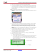
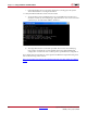
Setup the Local Area Network
1. Set up the Local Area Network on your PC as described in the topic Setting Up the
Local Area Network on the PC.
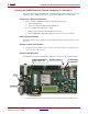
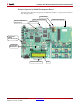
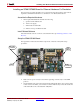
Setup the Spartan-3A DSP 1800A Starter Board
1. Position the Spartan-3A DSP 1800A Starter Board so the Xilinx logo is oriented
rightside up and located in the lower-right quadrant of the board.
2. Make sure the power switch, located in the upper-right corner of the board, is in the
OFF position.
3. If you are using a Xilinx Parallel Cable IV, follow steps 3a through 3d.
a. Connect the DB25 Plug Connector on the Xilinx Parallel Cable IV to the IEEE-1284
compliant PC Parallel (Printer) Port Connector.
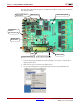
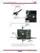
b. Using the narrow (14 pin) 6” High Performance Ribbon cable, connect the pod end
of the Xilinx Parallel Cable IV to the JTAG Port (J2) on the Starter Board.
c. Connect the attached Power Jack cable to the Keyboard/Mouse connector on the
PC.
d. If necessary, connect the male end of the Keyboard/Mouse cable to the associated
female connector on the Xilinx Power Jack cable (splitter cable).
4. If you are using a Xilinx Platform Cable USB, follow step 4a and 4b.
a. Connect the Xilinx Platform Cable USB to a USB port on the PC.
b. Using the narrow (14 pin) 6” High Performance Ribbon cable, connect the pod end
of the Xilinx Platform Cable USB to the JTAG Port (J2) on the Starter Board.