
User guide

System Generator for DSP User Guide www.xilinx.com 289
UG640 (v 12.2) July 23, 2010
Installing Your Board for Ethernet Hardware Co-Simulation
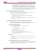
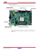
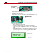
8. Set the SW3 Configuration Address DIP Switches.
Set the Configuration Address DIP Switches as follows:
1:on, 2:off, 3:off, 4:on, 5:off, 6:on, 7:off, 8:on
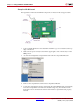
9. Set the Ethernet Mode Select jumpers
As shown below, connect pin 1 and 2 on both the Ethernet Mode Select jumpers (J22
and J23)
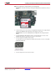
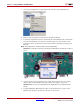
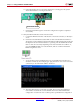
10. Verify the Configuration Settings
a. Turn the target board Power switch ON.
b. Check the on-board status LEDs to ensure the FPGA is configured. If the
configuration succeeded, the DONE LED should be on and all error LEDs should
be off.
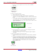
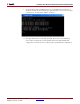
c. As shown below, check the information displayed on the 16-character 2-line LCD
screen of the board. If no error occurred, the Ethernet MAC address (without
colons) should appear on the first line of the display and the IPv4 address should
appear on the second line.
SW3 Configuration
Address
DIP Switches
(not yet configured)
Ethernet Mode Select
jumpers (J22 & J23)