
User guide

284 www.xilinx.com System Generator for DSP User Guide
UG640 (v 12.2) July 23, 2010
Chapter 3: Using Hardware Co-Simulation
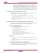
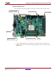
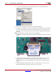
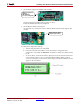
As shown below, set the Configuration Source Selector Switch to SYS ACE
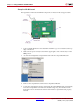
10. Verify the Configuration Settings
a. Turn the target board Power switch ON.
b. Check the on-board status LEDs to ensure the FPGA is configured. If the
configuration succeeded, the DONE LED should be on and all error LEDs should
be off.
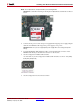
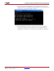
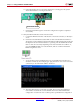
c. As shown below, check the information displayed on the 16-character 2-line LCD
screen of the board. If no error occurred, the Ethernet MAC address (without
colons) should appear on the first line of the display and the IPv4 address should
appear on the second line.
d. If the LCD display does not show the information correctly, press the System
ACE™ Reset button to reconfigure the FPGA.
e. Check the status LEDs again to ensure the configuration sequence completed
successfully.
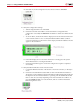
11. Verify the Ethernet Interface and Connection Status
a. Connect the Ethernet interface of the board to a network connection, or directly to
a host.
b. Check the on-board Ethernet status LEDs to make sure the Ethernet interface is
attached to an active Ethernet segment. The LEDs should reflect the link speed and
the duplex mode at which the interface is operating. The TX and RX leds should
flash on and off occasionally depending on the network traffic. If no LED is on,
press the CPU Reset button to reset the FPGA, and also examine whether the
Ethernet segment is active.