
User guide


272 www.xilinx.com System Generator for DSP User Guide
UG640 (v 12.2) July 23, 2010
Chapter 3: Using Hardware Co-Simulation
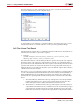
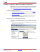
Once the dialog box is open, selecting the Shared Memories tab reveals information
about each shared memory in the compiled design.
Go ahead and leave the hardware co-simulation library open. In the next topic you will
include the hardware co-simulation block in a video processing testbench design.
5x5 Filter Kernel Test Bench
Included with the example files is a Simulink test bench model that uses the hardware co-
simulation block to filter a looped video sequence.
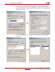
8. From the
$SYGEN/examples/shared_memory/hardware_cosim/conv5x5_video
directory, open conv5x5_video_testbench.mdl.
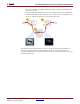
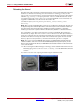
The testbench model uses a From Workspace block to produce the looped video sequence.
Each frame of the video sequence is represented as a 128x128 uint8 Simulink matrix (a
pre-load function loads and initializes the video sequence automatically when the model is
opened). Video frames are written into the FPGA Processing subsystem where they are
filtered at the rate of one frame per simulation cycle. The filtered output is then written to
a Matrix Viewer block for analysis.
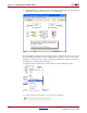
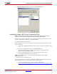
The FPGA Processing subsystem contains a stub for the hardware co-simulation block,
as well as Shared Memory Read and Write blocks. In this example, the Shared Memory
Read and Write blocks are responsible for managing video frame I/O to and from the
shared memories operating inside the FPGA. The operation of these blocks is described
below:
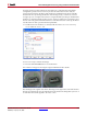
a. The Shared Memory Write block wakes up and requests lock of the input buffer
lockable shared memory Foo. Once lock is granted, the block writes the video
frame data input into the lockable shared memory and releases lock.
b. The hardware co-simulation block wakes up and requests lock of the input and
output buffer shared memories Foo and Bar. The host PC shared memory images
are transferred to the FPGA and lock is granted. The FPGA processes the input
buffer data and writes the output into the output buffer. Lastly the FPGA releases