
User guide


270 www.xilinx.com System Generator for DSP User Guide
UG640 (v 12.2) July 23, 2010
Chapter 3: Using Hardware Co-Simulation
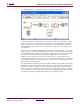
128. If you decide to process a different size frame, the Line Size parameter should be
updated accordingly.
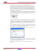
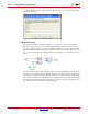
Valid Bit Generation
The data path includes a subsystem named valid_generator that is responsible for
driving the din_valid port of the output buffer block. The subsystem has two inputs,
valid_in and offset. The valid_in port is driven by the dout_valid signal from the
input buffer block, which is delayed by a variable number of cycles before it is driven to the
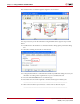
valid_out port. The logic associated with the valid_generator subsystem is shown
below.
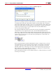
An addressable shift register block (ASR) is used to delay the valid bit. The offset port is
used to control the address of the ASR block, which in turn controls the amount of latency
the valid bit incurs. By simply delaying the valid bit generated by the input buffer block,
You ensure the number of words written to the output buffer is always equal to the buffer
size. Note that when the design is run in hardware, a change in the offset value will cause
the vertical alignment of the filtered images to change.