
User guide


268 www.xilinx.com System Generator for DSP User Guide
UG640 (v 12.2) July 23, 2010
Chapter 3: Using Hardware Co-Simulation
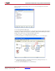
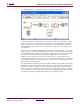
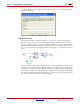
from the host PC, through the interface, and back to the host PC. Operation of the I/O
buffering interface is shown in the flow chart below:
Notice that the buffering interface design includes several data valid ports. These ports are
used for data flow control. A "true" output from the Input Buffer dout_valid port
indicates new data is ready to be processed by the data path. Likewise, when the data path
is finished processing the data, it should drive the Output Buffer subsystem's
din_valid port to "true" to indicate valid output data (the din_valid port is analogous to
a write enable control signal).
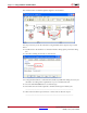
The example includes a placeholder that should be replaced by a System Generator data
path. You may insert any data path in the buffer interface provided that it works within the
valid signal semantics described above.